Method and system for controlling cooling system of power equipment

a technology of cooling system and power equipment, which is applied in the direction of computer control, program control, instruments, etc., can solve the problems of low copper loss of winding, higher power consumption of cooling system, and low overall efficiency

Active Publication Date: 2018-10-04
HITACHI ENERGY SWITZERLAND AG
View PDF0 Cites 1 Cited by
  • Summary
  • Abstract
  • Description
  • Claims
  • Application Information

AI Technical Summary

Benefits of technology

The invention provides a method for controlling a cooling system for a power equipment through a series of steps. The method involves obtaining data sets related to the power equipment and its cooling system during a first and second load cycle, and using these data sets to establish optimal cooling capacity parameters for the cooling system. The optimal cooling capacity parameters are then used to control the cooling system during a present load cycle. The method can make use of historical data and statistical information to prepare precise and intelligent measure plans for the cooling system. The result is an efficient cooling system that reduces the time and cost of operation.

Problems solved by technology

For example, normally, lower winding temperature leads to the lower copper loss of winding.
However, the power consumption of the cooling system will be higher at the same time, meaning that the overall efficiency, considering both power equipment winding and the cooling system itself, might be less optimal.
The more frequent the temperature varies, the faster the power equipment aging will be.
It could be so that the efficiency of the power equipment is optimized, however at a cost of shortened lifetime.
However, because the response of interest for previous time intervals will have effect upon the subsequent, separate optimization design based on the quantitative model might not suffice for optimal criteria for an operation efficiency objective concerning a load cycle of a power equipment.
Such temperature difference will accumulate step-by-step for the computation of the response of interest concerning the time intervals of the load cycle subsequent to the initial time interval n, which will gradually increase transformer power loss and life loss.
Therefore, even if the optimization algorithm in terms of each of the time intervals can achieve the best result at every time internal, not necessarily the best for an entire load cycle.

Method used


Image

  • Method and system for controlling cooling system of power equipment
  • Method and system for controlling cooling system of power equipment
  • Method and system for controlling cooling system of power equipment

Examples


Embodiment Construction

[0018]In the following description, for purposes of explanation and not limitation, specific details are set forth, such as particular circuits, circuit components, interfaces, techniques, etc. in order to provide a thorough understanding of the present invention. However, it will be apparent to one skilled in the art that the present invention may be practiced in other embodiments that depart from these specific details. In other instances, detailed descriptions of well-known methods and programming procedures, devices, and circuits are omitted so not to obscure the description of the present invention with unnecessary detail.

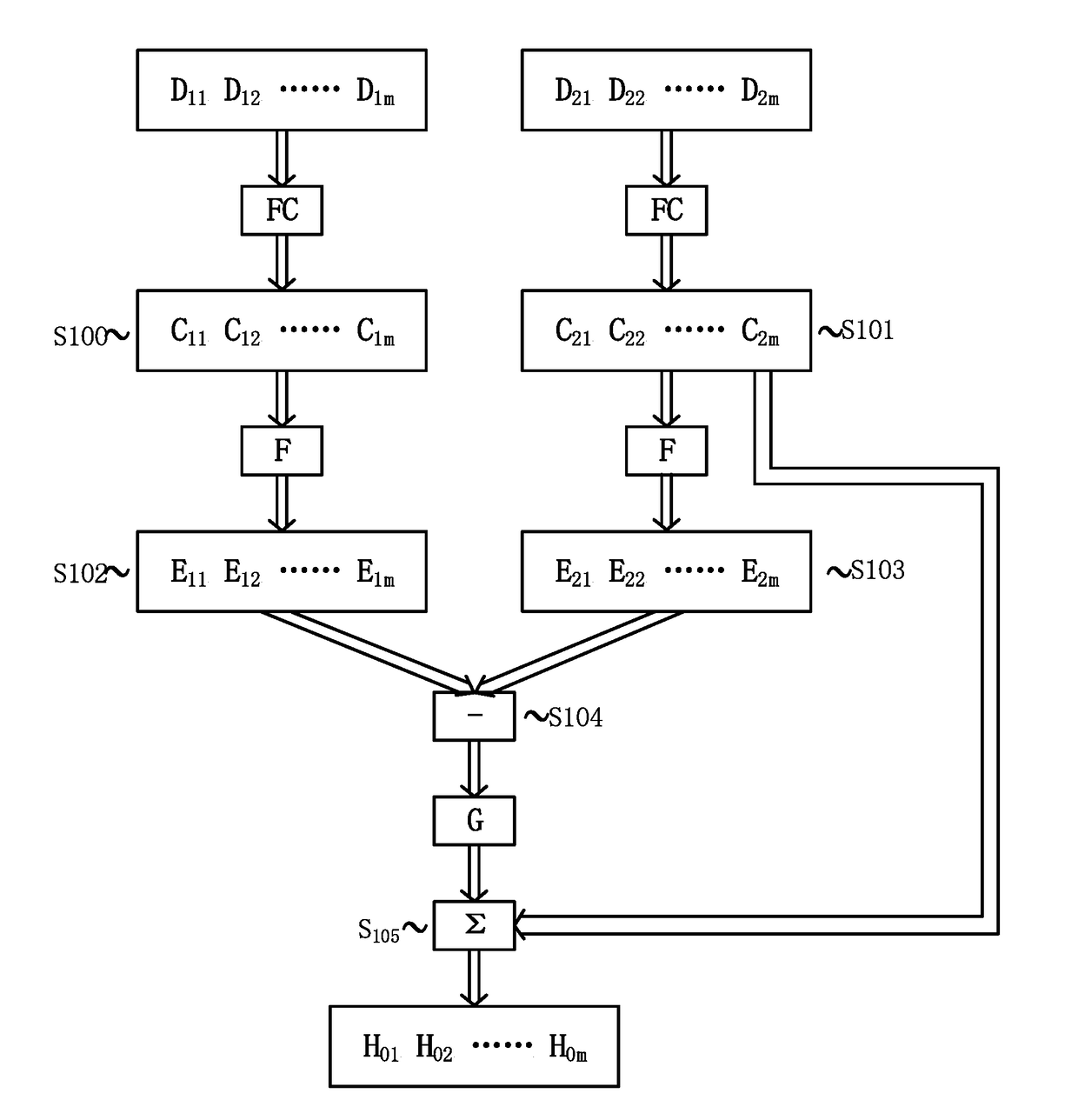
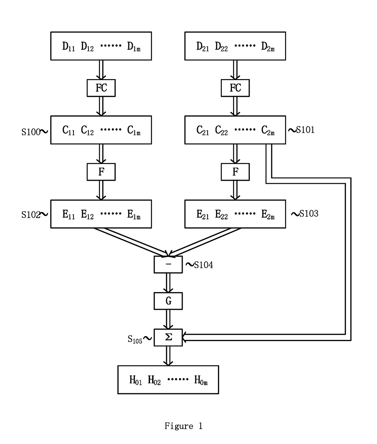
[0019]FIG. 1 illustrates a method for controlling cooling system of a power equipment according to an embodiment of present invention. For example, the power equipment is a power transformer. As shown in FIG. 1, operational cost related parameters Powerloss, Lifeloss, Noisereductionloss respectively for a first load cycle and a second load cycle in the history...


PUM


Abstract

A method for controlling cooling system of a power equipment and a system using the same. The method includes steps of: obtaining a first data set representing operational cost related parameters specific to the power equipment and its cooling system at a series of time intervals of a first load cycle in a history profile; obtaining a second data set representing operational cost related parameters specific to the power equipment and its cooling system at a series of time intervals of a second load cycle in the history profile, where the second load cycle follows the first load cycle; in consideration of the parameters represented by the first data set, through knowledge-based predetermined numerical and / or logical linkages, establishing a third data set representing optimal cooling capacity parameters for the cooling system at the series of time intervals of the first load cycle according to criteria for operational cost optimization of the power equipment; in consideration of the parameters represented by the second data set, through knowledge-based predetermined numerical and / or logical linkages, establishing a fourth data set representing optimal cooling capacity parameters for the cooling system at the series of time intervals of the second load cycle according to criteria for operational cost optimization of the power equipment; establishing a fifth data set representing a cooling capacity parameter difference between the established cooling capacity parameters concerning the first load cycle and the second load cycle; establishing a sixth data set representing cooling capacity parameters for the cooling system at a series of time intervals of a present load cycle by computationally correcting the established cooling capacity parameter concerning the time intervals of the second cycle load with use of the cooling capacity parameter difference; and controlling the cooling system to operate at a series of time intervals of the present load cycle at the stablished cooling capacity parameters concerning the present load cycle represented by the sixth data set.

Description

TECHNICAL FIELD[0001]The invention relates to control of temperature of a power equipment, and more particularly to control of temperature of a power equipment with digital data processing.BACKGROUND ART[0002]Power equipment, for example, can be power transformer, machine and so on, whose losses vary with its loading level, and substantial part of its losses is converted into heat. Due to higher power ratings, power equipment is often cooled by forced-air cooling, forced-oil cooling, water-cooling, or combinations of these. Therefore, the power equipment needs a cooling system which, for example, can be an arrangement of at least one fan or blower pumping cooling-air or liquid coolants as oil and water. The practice of slowing down or speeding up cooling system to keep temperature of a power equipment within a predetermined range is common and there are numerous technologies that accomplish this.[0003]An operation efficiency of the power equipment is influenced by several parameters...

Claims


Application Information

Patent Timeline
IPC IPC(8): H01F27/08H05K7/20H01F27/33H01F27/00G05B19/408
CPCH01F27/085H05K7/20209H01F27/33H01F27/008G05B19/408G06Q50/06G06F1/20G06F1/206H01F27/08Y02D10/00
Inventor CHEN, YAOCHEN, NIYAYU, RONGRONG
Owner HITACHI ENERGY SWITZERLAND AG
Why Eureka
Try Eureka