
Part mounting position guidance device, part mounting position guidance system, and part mounting position guidance method

a technology of mounting position and guidance device, which is applied in the direction of electrical appliances, electric programme control, instruments, etc., can solve the problems of difficult recognition of the mounting position of the part and the unit, and achieve the effect of short tim

Active Publication Date: 2018-10-04
FANUC LTD
View PDF0 Cites 282 Cited by
  • Summary
  • Abstract
  • Description
  • Claims
  • Application Information

AI Technical Summary

Benefits of technology

The present invention provides a device that helps an operator easily find the position where a part is to be mounted in a complex machine structure. This device helps to save time and improve efficiency in repairing or replacing parts in machines.

Problems solved by technology

However, when a structure significantly varies depending on a manufacturer, and a machine is a machine tool having a complexed structure, or the like, it is often that, although an operator who actually operates is acquainted with places in a machine that are operated in normal times, such operator is unfamiliar with structures of a side surface and a rear surface of the machine.
Thus, even if a defective part and a unit including the defective part are specified, when the part and the unit are in a side surface or a rear surface, mounting positions of the part and the unit are difficult to be recognized.

Method used


Image

  • Part mounting position guidance device, part mounting position guidance system, and part mounting position guidance method
  • Part mounting position guidance device, part mounting position guidance system, and part mounting position guidance method
  • Part mounting position guidance device, part mounting position guidance system, and part mounting position guidance method

Examples


first embodiment

Effect of First Embodiment

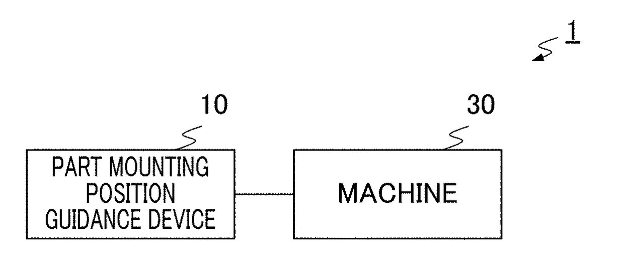
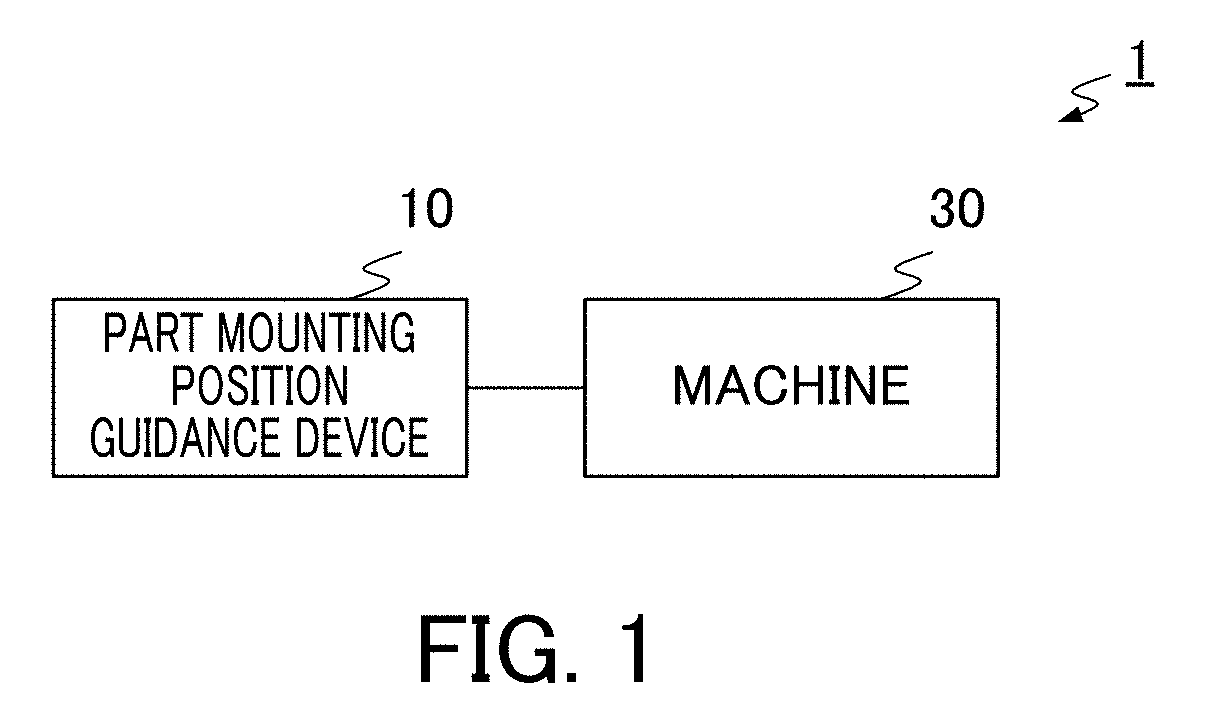
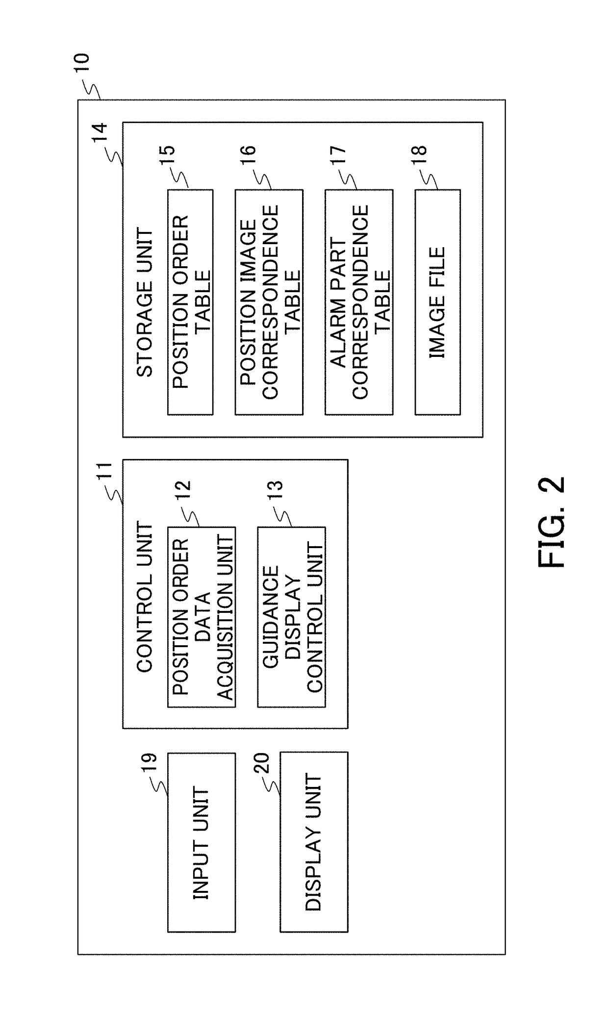
[0065]According to the present embodiment, the control unit 11 of the part mounting position guidance device 10 includes the position order data acquisition unit 12 and the guidance display control unit 13. The position order data acquisition unit 12 refers to the position order table 15, the position image correspondence table 16, the alarm part correspondence table 17, and the image file 18 to acquire the position order data from the storage unit 14. The guidance display control unit 13 causes the display unit 20 to display in order, the images indicating one or more pieces of position information from the image indicating the predetermined position of the machine 30 to the image indicating the mounting position of the part, on the basis of the position order data acquired by the position order data acquisition unit 12. Thereby, the part mounting position guidance device 10 guides from the machine position in which the operator usually operates to the mou...

second embodiment

Effect of Second Embodiment

[0077]In the present embodiment, the machine 40 itself has the same function as that of the part mounting position guidance device 10 according to the first embodiment. More particularly, the machine 40 includes a control device 41 including the same function as that of the control unit 11 of the part mounting position guidance device 10, a storage device 42 including the same data as that of the storage unit 14 of the part mounting position guidance device 10, and a display device 43 having the same function as that of the display unit 20 of the part mounting position guidance device 10. Thereby, the operator of the machine 40 can quickly specify a mounting position of a defective part only by operation to the same machine when an alarm is issued during the operation of the machine 40.

Third Embodiment

[0078]Hereinafter, a third embodiment of the present invention will be described with reference to FIG. 8. The third embodiment is a system that guides a mou...

third embodiment

Effect of Third Embodiment

[0083]In the present embodiment, one part mounting position guidance device 10 can guide a mounting position of a part of one or more machines 30. Thereby, an operator who manages the one or more machines 30, can check only the display unit 20 of the part mounting position guidance device 10 to recognize in order, the position information from the predetermined position of the one or more machines 30 to the mounting position.

Modification

[0084]The embodiments of the present invention are described above. However, the present invention is not limited to the embodiments described above. The effects described in the embodiments are only most suitable effects generated by the present invention listed. The effects of the present invention are not limited to hose described in the embodiments.

[0085]In the embodiments described above, the present invention is configured so that one part corresponds to one alarm. However, the configuration is not limited thereto. For...


PUM


Abstract

Provided is a part mounting position guidance device with which an operator can easily recognize a position of a machine in which a part or unit composing a machine having a complexed structure is mounted. The part mounting position guidance device includes a control unit which includes: a position order data acquisition unit that acquires position order data in which one or more pieces of position information of from a predetermined position of a machine to a mounting position of a part are ordered for each part composing the machine; and a guidance display control unit that causes a display unit to display in order, images indicating one or more pieces of position information from an image indicating the predetermined position of the machine to the image indicating the mounting position of the part, on the basis of the position order data acquired by the position order data acquisition unit.

Description

[0001]This application is based on and claims the benefit of priority from Japanese Patent Application. No. 2017-072132, filed on 31 Mar. 2017, the content of which is incorporated herein by reference.BACKGROUND OF THE INVENTIONField of the Invention[0002]The present invention relates to a part mounting position guidance device, a part mounting position guidance system, and a part mounting position guidance method for causing a display device to display a mounting position of a part composing a machine.Related Art[0003]In a conventional machine having a complexed structure, specifying a mounting position of a defective part is difficult even when an alarm is issued, and the defective part is specified. In regard to this, Patent Document 1 discloses a technique of displaying a drawing of a vehicle that is the same as a vehicle owned by a user, and specifying a defective portion of while utilizing a guidance, in order to specify the defective portion of the vehicle.[0004]Patent Docume...

Claims


Application Information

Patent Timeline
IPC IPC(8): G09B19/00G08B5/22G09B5/06
CPCG09B19/00G08B5/22G09B5/065G05B19/04H04L41/0631
Inventor KAMIGUCHI, MASAOKAWAKAMI, SHOUICHINORO, AMANE
Owner FANUC LTD
Learn More