Inductive and conductive onboard charging systems

a charging system and inductive and conductive technology, applied in the field of charging systems, can solve the problems of logistically challenging more complex systems using this option

Active Publication Date: 2018-10-04
GM GLOBAL TECH OPERATIONS LLC
View PDF3 Cites 9 Cited by
  • Summary
  • Abstract
  • Description
  • Claims
  • Application Information

AI Technical Summary

Benefits of technology

The patent text describes an onboard charging system for electric vehicles that can be charged from a power source. The system includes a coupling device, charging circuit, rectifier, converter, and inductive receiver. The charging circuit connects the coupling device to the power source, and the rectifier converts the AC power to DC. The converter boosts the DC voltage, and the inductive receiver induces current from a source across an air gap. The technical effects of the system include improved charging efficiency and flexibility, as well as reduced charging time and cost.

Problems solved by technology

Using this option may be logistically challenging for more complex systems.

Method used


Image

  • Inductive and conductive onboard charging systems
  • Inductive and conductive onboard charging systems
  • Inductive and conductive onboard charging systems

Examples


Embodiment Construction

[0013]The following detailed description is merely exemplary in nature and is not intended to impart limitations. Furthermore, there is no intention to be bound by any theory presented in the preceding sections, or the following detailed description.

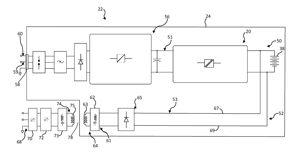
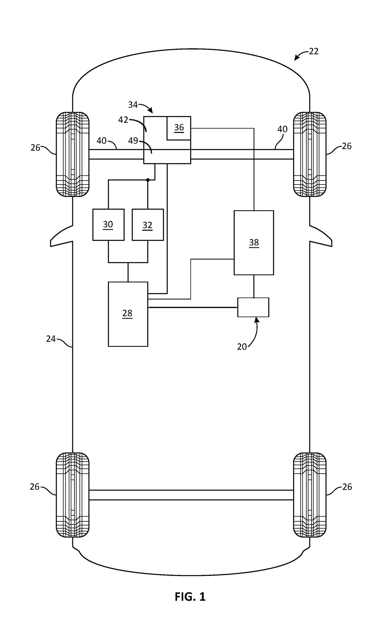
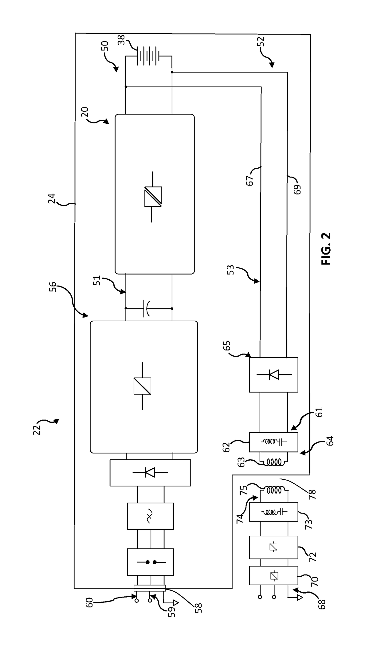
[0014]In a number of examples, an ESS charging system 20 may be employed in a power unit, which may be any unit that uses an ESS for which charging may be needed. The power unit may, for example, be a vehicle, a generator, a portable power supply, or any ESS powered equipment whether mobile, portable or stationary. In a number of examples, the power unit may be a vehicle 22, such as indicated in FIG. 1. The vehicle 22 may be any one of a number of different types of land, sea, or air vehicles, and in certain embodiments, may for example, be a passenger automobile of any configuration. As depicted in FIG. 1, the vehicle 22 may include, in addition to the above-referenced ESS charging system 20, any, or any combination of: a body 24, wheel...


PUM


Abstract

An onboard charging system for charging from a power source may include an energy storage system. A connector may be configured to couple the onboard charging system with the power source. A charging circuit may be electrically connected between the connector and the energy storage system. A converter may be electrically connected in the charging circuit between the connector and the energy storage system. A rectifier may be electrically connected in the charging circuit between the connector and the converter. Output of an inductive receiver may be electrically connected with the charging circuit between the connector and the converter. The converter may control the delivery of voltage and current to the energy storage system from the power source and from the inductive receiver.

Description

INTRODUCTION[0001]The present invention generally relates to charging systems, and more particularly relates to inductive and conductive onboard charging systems.[0002]When an energy storage system (ESS), such as a battery system, is used in mobile applications, a convenient approach to reversing the depletion of the ESS is needed. The depleted ESS, or the rechargeable part thereof, may be physically exchanged with a charged unit. Exchange requires availability of compatible battery packs and a system designed to accommodate exchange. Using this option may be logistically challenging for more complex systems. Another option may involve the use of an offboard system where the principle components of the charger are offboard. This type of approach may use charging stations or other types of charging facilities. An offboard charging system requires connection with componentry on the mobile unit, and therefore compatibility is required. Another option may be an onboard system where the ...

Claims


Application Information

Patent Timeline
Patent Type & Authority Applications(United States)
IPC IPC(8): B60L11/18H02J7/06H02J7/02
CPCB60L11/1812H02J7/06H02J2007/10B60L11/182B60L11/1816H02J7/025B60L53/12B60L53/20B60L53/60B60L53/14B60L2210/30B60L53/22H02J50/12H02J2310/48H02J7/02H02J2207/20Y02T10/70Y02T90/12Y02T10/7072Y02T90/14Y02T10/72
Inventor ALBANNA, AHMADANWAR, MOHAMMAD N.CICHY, STEPHEN M.NAMOU, ANDREW J.
Owner GM GLOBAL TECH OPERATIONS LLC
Why Eureka
Try Eureka