
Vacuum systems for hair clippers

a vacuum system and hair clipper technology, applied in the direction of metal working devices, etc., can solve the problems of long hair stuck in the air inlet, small debris can be lost, etc., and achieve the effect of better trapping of small debris and high air flow

Active Publication Date: 2018-10-04
WAHL CLIPPER
View PDF7 Cites 4 Cited by
  • Summary
  • Abstract
  • Description
  • Claims
  • Application Information

AI Technical Summary

Benefits of technology

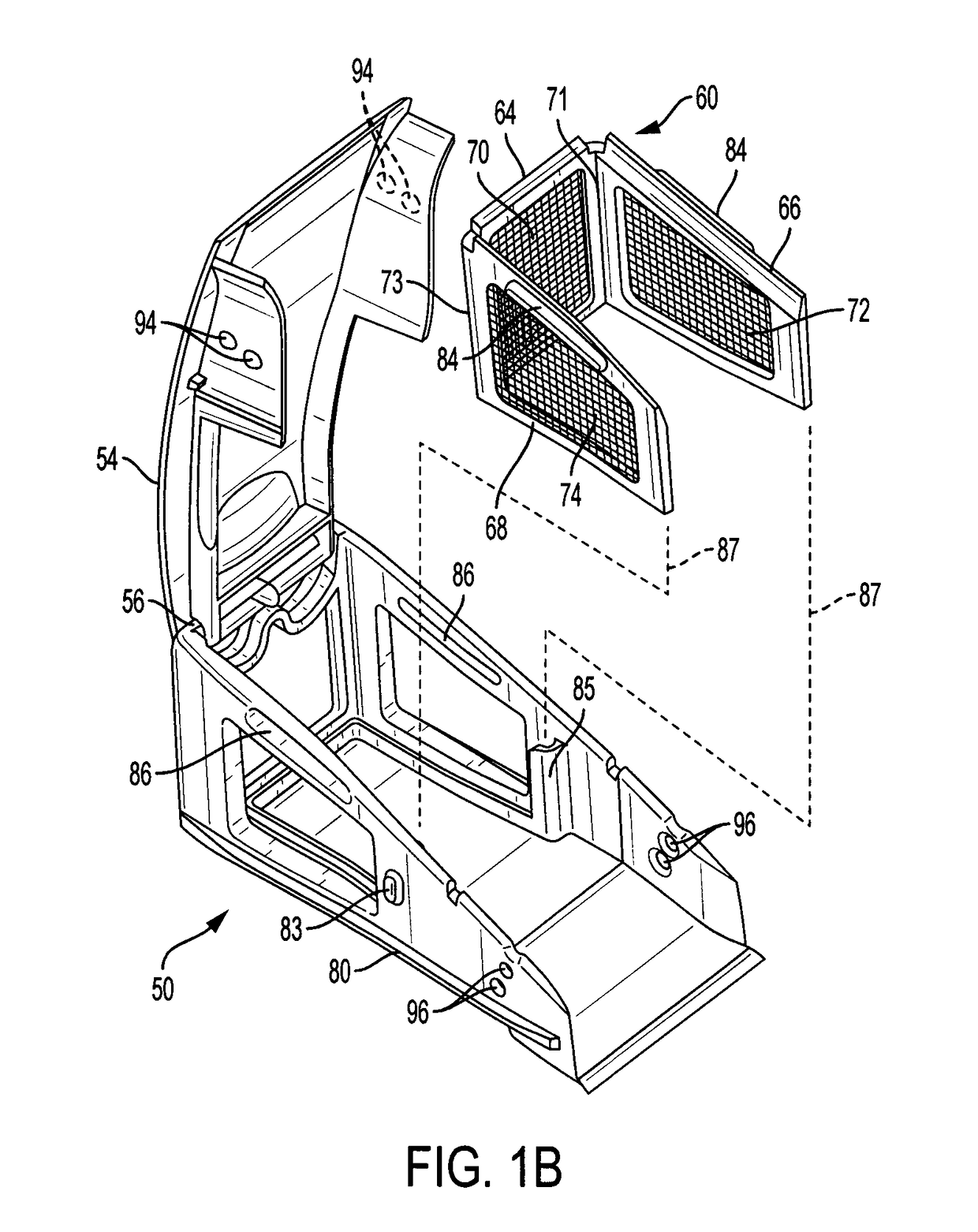
The invention allows for adjustment of the air inlet near the cutting blades to provide better trapping of small debris with a small opening and collect larger debris with a larger opening, as needed. This improves the performance of the cutting tool.

Problems solved by technology

However, a large air inlet draws large debris well, but small debris can be lost because negative air pressure at the inlet is relatively low.
A small air inlet creates a strong vacuum, which attracts small hair particles, but longer hair can get stuck in the air inlet, because it is small.

Method used


Image

  • Vacuum systems for hair clippers
  • Vacuum systems for hair clippers
  • Vacuum systems for hair clippers

Examples


Embodiment Construction

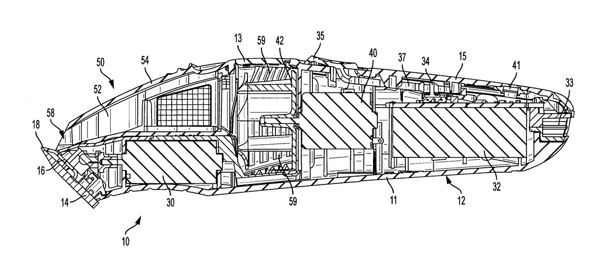
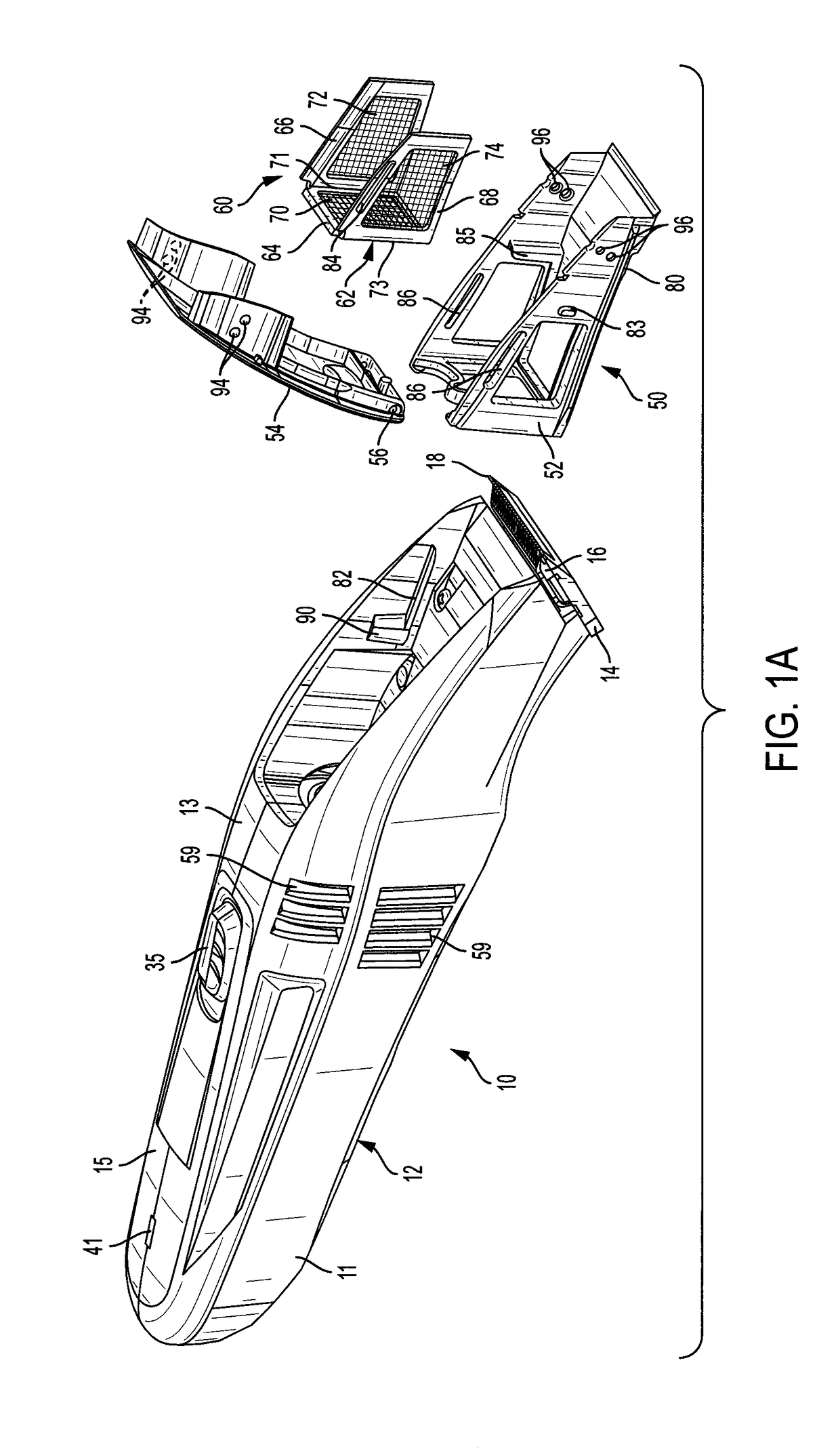
[0027]As seen in FIGS. 1 and 2, a hair clipper 10 has a housing 12 that includes a bottom case 11, a top lid 13 and a switch panel 15. The hair clipper 10 also has a stationary blade 14 and a reciprocating blade 16. Both blades have complimentary rows of cutting teeth at an end 18. The cutting blades 14, 16 are secured to the bottom case 11 of the housing 12 in any suitable manner, such as retaining ribs or screws. The blades are secured outside of the housing.

[0028]The reciprocating blade 16 is driven back and forth by a motor 30 (FIG. 2), which is powered by a battery 32 through an electrical switch 34. A charging port 33 can be provided, as well as an LED 41 to indicate the battery state, power status and the like.

[0029]A vacuum system includes another motor 40 having a fan 42 that generates air flow in the housing, as will be described. The motor 40 is also powered by the battery 32 through the switch 34. The switch 34 is part of a switch assembly that controls power to the moto...


PUM


Abstract

A hair clipper has a vacuum system for collecting hair debris created by the cutting blades. Air flow through an adjustable air inlet is divided into multiple paths, including at least one primary flow path and at least one separate secondary flow path. A debris trap intersects both the primary air flow path and the secondary air flow path. The primary flow path allows air flow through the first path to be higher than a secondary air flow through the second path before debris accumulates in the debris trap. The primary air flow decreases as debris accumulates in the primary air flow path and the secondary air flow approaches and perhaps exceeds the primary air flow, whereupon some debris accumulates in the secondary air flow path as air is diverted through the secondary air flow path.

Description

[0001]This invention relates to vacuum systems for hair clippers, and more particularly, to debris traps for hair clipper vacuum systems, and adjustable air inlets for hair clipper vacuum systems.BACKGROUND OF THE INVENTION[0002]Conventional vacuum systems for hair clippers have a debris trap that catches hair fragments as the hair is cut. However, airflow decreases as debris accumulates in the trap, which reduces airflow and inhibits waste accumulation Thus, there is a need for debris traps that maintain better waste accumulation as the trap fills with debris.[0003]Hair clippers and trimmers sometime create cut long hair strands. At other times, they create small debris, such as beard stubble. Conventional vacuum systems for hair clippers have a fixed air inlet adjacent the cutting blades to catch all of the debris. However, a large air inlet draws large debris well, but small debris can be lost because negative air pressure at the inlet is relatively low. A small air inlet creates...

Claims


Application Information

Patent Timeline
Patent Type & Authority Applications(United States)
IPC IPC(8): B26B19/44B26B19/06B26B19/38
CPCB26B19/44B26B19/3886B26B19/06
Inventor SNOW, GARY
Owner WAHL CLIPPER
Learn More