Light-receiving optical system
a technology of optical system and light, applied in the direction of optical radiation measurement, instruments, lenses, etc., can solve the problem of complicated configuration of the apparatus
- Summary
- Abstract
- Description
- Claims
- Application Information
AI Technical Summary
Benefits of technology
Problems solved by technology
Method used
Image

Examples
example 1
[0081]In Example 1, each of the annular sections of the multifocal Fresnel lens 300 is formed with continuous surfaces, and the light-receiving optical system is not provided with collective lenses.
[0082]The entrance pupil diameter D of the imaging optical system 200, the range of angle α of rays entering a single annular section, the maximum value αmax of half angle of view for receiving light of the imaging optical system 200, the annular section width w, the radius W of the multifocal Fresnel lens, the radius rd of the light-receiving elements and the distance Pd between the center of the light-receiving element most distant from the axis AX2 and the axis AX2 are determined as below.
D=2.2 [min]
α=0.25 [deg]=4.363E-03 [rad]
αmax=1.25 [deg]
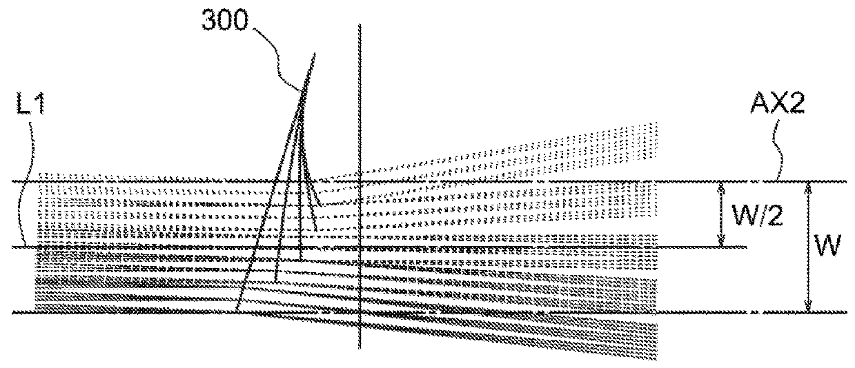
w=0.6 [min]
W=3.0 [min]
rd=0.25 [mm]
Pd=1.5 [min]
[0083]In this case, the right side of Expression (9) is 0.003191, and therefore Expression (9) is satisfied.
[0084]Further, the left side of Expression (16) is 0.048 [mm], and the right side of Expressio...
example 2
[0100]In Example 2, each of the annular sections of the multifocal Fresnel lens 300 is formed with continuous surfaces, and the light-receiving optical system is provided with collective lenses.
[0101]The entrance pupil diameter D of the imaging optical system 200, the range of angle αmax of rays entering a single annular section, the maximum value αmax of half angle of view for receiving light of the imaging optical system 200, the annular section width w, the radius W of the multifocal Fresnel lens, the radius rc of the collective lens, the radius rd of the light-receiving elements and the distance Pd between the center of the light-receiving element most distant from the axis AX2 and the axis AX2 are determined as below.
D=4.0 [mm]
α=0.45 [deg]=7.8540E-03 [rad]
αmax=2.25 [deg]
w=0.66 [min]
W=3.3 [min]
rc=3.0 [mm]
rd=0.25 [mm]
Pd=12.0 [mm]
[0102]In this case, the right side of Expression (9) is 0.003191, and therefore Expression (9) is satisfied.
[0103]Further, the left side of Expression (1...
example 3
[0124]The light-receiving optical system of Example 3 is identical with the light-receiving optical system of Example 1 except for the multifocal Fresnel lens. Each of the annular sections of the multifocal Fresnel lens of Example 3 is in the shape of a Fresnel lens. With this configuration, the amount of sag of the Fresnel surface can be reduced, and thereby the thickness of the multifocal Fresnel lens can be reduced.
[0125]Table 7 shows data of the shapes of the surfaces of the respective annular sections of the multifocal Fresnel lens 300. Unit of length in Table 7 is millimeter.
TABLE 7Annular sections12345R(=1 / c)10.35710.39110.34010.42210.416k−1−1−1−1−1dy−1.5−0.7500.751.5rmin00.61.21.82.4rmax0.61.21.82.43
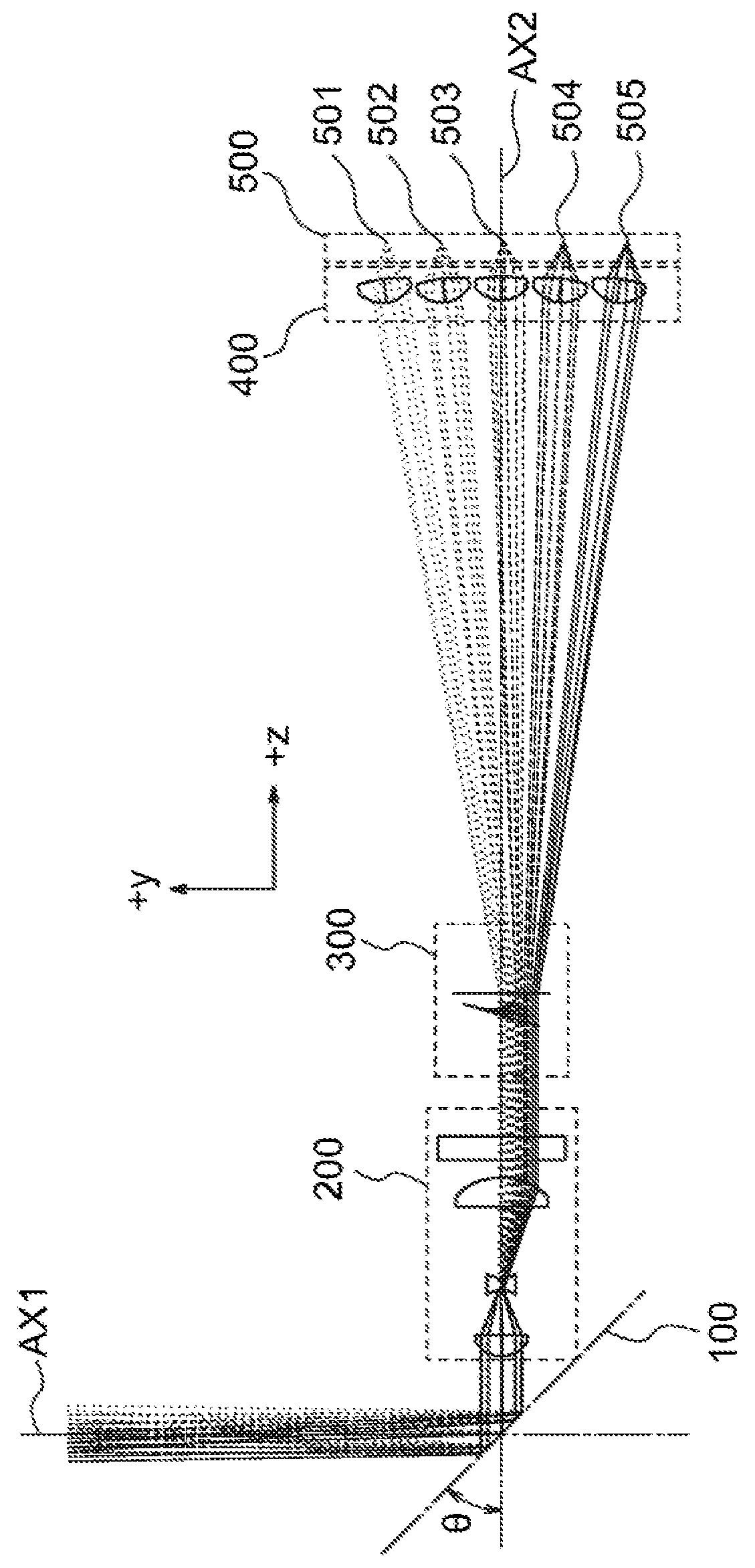
[0126]Numbers 1 to 5 in the upmost line in Table 7 represent respective annular sections that corresponds to 301 to 305 in FIG. 4. The pitch of the Fresnel lens of each annular section is 0.3 mm.
[0127]The surface of each annular section of the multifocal Fresnel lens 300 can be e...
PUM
 Abstract
Description
Claims
Application Information
 - R&D
- Intellectual Property
- Life Sciences
- Materials
- Tech Scout
- Unparalleled Data Quality
- Higher Quality Content
- 60% Fewer Hallucinations
Browse by: Latest US Patents, China's latest patents, Technical Efficacy Thesaurus, Application Domain, Technology Topic, Popular Technical Reports.
© 2025 PatSnap. All rights reserved.Legal|Privacy policy|Modern Slavery Act Transparency Statement|Sitemap|About US| Contact US: help@patsnap.com