
Obstacle detection device, traveling apparatus, obstacle detection system, and obstacle detection method

a technology of obstacle detection and detection device, which is applied in the direction of measurement device, scene recognition, instruments, etc., can solve problems such as being incapable of detection

Active Publication Date: 2018-09-20
SHARP KK
View PDF18 Cites 9 Cited by
  • Summary
  • Abstract
  • Description
  • Claims
  • Application Information

AI Technical Summary

Benefits of technology

This patent describes an obstacle detection device for a traveling apparatus, such as a robot, that has two units for detecting obstacles. The first unit detects obstacles within a certain range, while the second unit detects them using different processing. The two units have overlapping detection ranges, so the device can change its detection condition based on the results from the first unit to improve accuracy. This allows the device to detect obstacles that are closer to the traveling apparatus and with greater accuracy.

Problems solved by technology

However, if a substance (for example, a dry leaf, snow, a stone, or projections and depressions of a vehicle body) is put on a portion of an ultrasonic sensor, at which sound waves are emitted, or something (for example, mud, sand, or snow) adheres to the portion, a decision may be made due to erroneous sensing to stop traveling despite the absence of a problem with traveling.
The technique, however, suffers from the problem of becoming incapable of detection if something is put in front of a detection unit of the sensor or something (for example, mud, sand, or snow) adheres during traveling.

Method used


Image

  • Obstacle detection device, traveling apparatus, obstacle detection system, and obstacle detection method
  • Obstacle detection device, traveling apparatus, obstacle detection system, and obstacle detection method
  • Obstacle detection device, traveling apparatus, obstacle detection system, and obstacle detection method

Examples


first embodiment

[0026]Modes for implementing provision of a traveling apparatus having a mounted obstacle detection device according to the present disclosure will be described below with reference to the drawings.

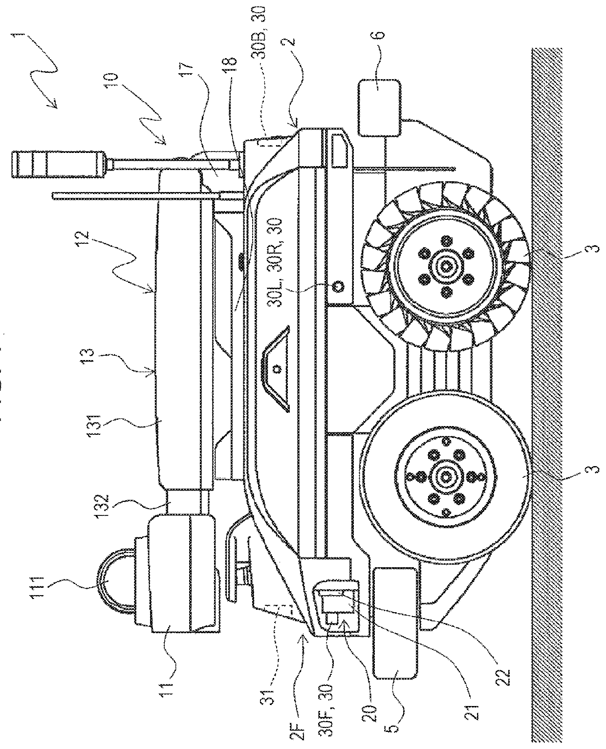
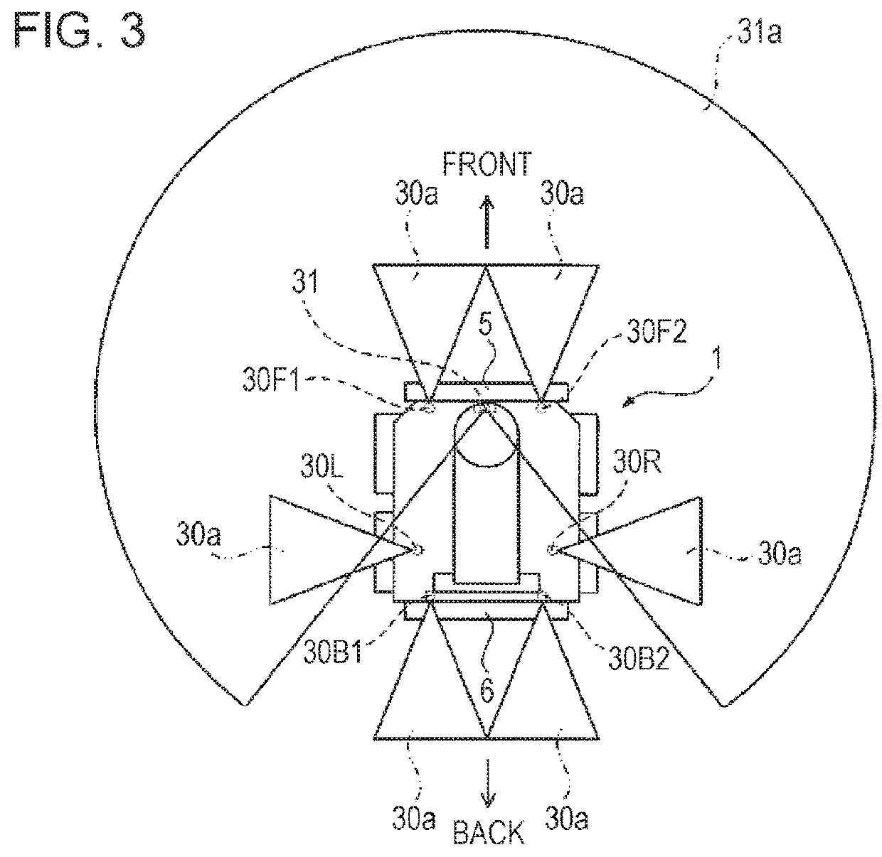
[0027]FIG. 1 shows an example of a mode for carrying out the disclosure and is an explanatory view in side view showing an overall configuration of a traveling apparatus according to a first embodiment. FIG. 2 is an explanatory view showing a state of installation of ultrasonic sensors in the traveling apparatus, and FIG. 3 is an explanatory view showing detection regions for the ultrasonic sensors in the traveling apparatus.

[0028]A traveling apparatus 1 according to the first embodiment is a traveling apparatus functioning as an autonomous traveling vehicle having a mounted obstacle detection device which includes a plurality of obstacle detection units configured to detect an obstacle in surroundings of the apparatus and a control unit configured to control detection by the obstacle det...

second embodiment

[0079]A second embodiment will next be described with reference to the drawings.

[0080]FIG. 9 is an explanatory view showing an example of a state of obstacle detection by ultrasonic sensors and a LIDAR sensor in a traveling apparatus according to the second embodiment.

[0081]Note that the traveling apparatus according to the second embodiment has the same configuration as that of the traveling apparatus according to the first embodiment and is different in control by an obstacle detection device. Same components are denoted by same reference characters, and a description thereof will be omitted.

[0082]As shown in FIG. 9, a traveling apparatus 201 according to the second embodiment is characteristically configured to determine the presence or absence of an obstacle on the basis of a detection result from an ultrasonic sensor 30 without using a detection result from a LIDAR sensor 31 if an obstacle 86 which is present within a detection range for the ultrasonic sensor 30 and a detection...

third embodiment

[0085]A third embodiment will next be described with reference to the drawings.

[0086]FIG. 10 is a block diagram showing an electrical configuration of a traveling apparatus according to the third embodiment.

[0087]Note that the traveling apparatus according to the third embodiment has the same basic configuration as that of the traveling apparatus 1 according to the first embodiment and that a description thereof will be omitted.

[0088]As shown in FIG. 10, a traveling apparatus 301 according to the third embodiment characteristically has the configuration below in addition to the configuration of the traveling apparatus 1 according to the first embodiment. If a person is detected by an ultrasonic sensor 30 and a LIDAR sensor 31 at the start of detection action by the ultrasonic sensor 30 and the LIDAR sensor 31, and detection of the person is not confirmed by the ultrasonic sensor 30 and the LIDAR sensor 31 after that, it is determined that the person has moved away.

[0089]As shown in ...


PUM


Abstract

A traveling apparatus has a mounted obstacle detection device including a plurality of obstacle detection units configured to detect an obstacle and a control unit configured to control detection by the obstacle detection units. The obstacle detection device includes, as the obstacle detection units, an ultrasonic sensor and a LIDAR sensor. The LIDAR sensor is configured to be capable of detecting an obstacle within a detection range for the ultrasonic sensor and detecting an obstacle within a range which extends farther than the detection range for the ultrasonic sensor. The control unit controls detection such that, if a detection range for either one of the ultrasonic sensor and the LIDAR sensor becomes undetectable, the other sensor complements the undetectable range.

Description

BACKGROUND1. Field[0001]The present disclosure relates to an obstacle detection device, a traveling apparatus, an obstacle detection system, and an obstacle detection method and, more particularly, to an obstacle detection device, a traveling apparatus, an obstacle detection system, and an obstacle detection method including an obstacle detection unit configured to detect an obstacle in surroundings of the apparatus.2. Description of the Related Art[0002]Known conventional traveling apparatuses having a mounted monitoring device include an autonomous traveling vehicle including an information detection unit which detects information on surroundings of the vehicle.[0003]Known autonomous traveling vehicles (for example, a self-propelled robot) include one which measures a distance to an obstacle in surroundings of the vehicle by driving a plurality of mounted detection elements (information detection units).[0004]In a case using an ultrasonic sensor as a detection element, a plurality...

Claims


Application Information

Patent Timeline
Patent Type & Authority Applications(United States)
IPC IPC(8): G01S17/93G06K9/00G01S17/89G01S15/931G01S15/86G01S17/86G01S17/931
CPCG01S17/936G06K9/00805G01S17/89G01S15/931G01S17/931G01S15/04G01S17/86G01S15/86G06V20/58
Inventor KURODA, TATSURO
Owner SHARP KK
Learn More