
Oil supply device for an epicyclic reduction gear set

a technology of epicyclic reduction and oil supply device, which is applied in the direction of gearing details, machines/engines, and efficient propulsion technologies, etc., can solve the problems of affecting maintenance, affecting the stability of the turbine engine, and the reduction gear system is not readily compatible with the flexible installation of the structure of the turbine engin

Active Publication Date: 2018-09-13
SAFRAN TRANSMISSION SYST
View PDF0 Cites 19 Cited by
  • Summary
  • Abstract
  • Description
  • Claims
  • Application Information

AI Technical Summary

Benefits of technology

The patent is for a new design for a lubricant distribution system for turbine engines. The design includes a bowl with multiple cups placed around its edge. These cups are separated from each other, allowing for separate control of the flow of lubricant to different parts of the engine. This design reduces the need for a special injector, increases reliability, and simplifies the oil distribution system. The design also ensures good rotation of the lubricant and minimizes oil consumption. Overall, this design improves performance and reliability of the turbine engine.

Problems solved by technology

However, they have the drawback that they have planet pinions that revolve around the rotation axis of the drive shaft of the reduction gear.
These systems have the drawbacks of being bulky, and their wear is incompatible with the service life required for aeronautical engines, which affects the maintenance of said engines.
Finally, these reduction gear systems are not readily compatible with flexible installation of the structure of the turbine engine, recommended for example for overcoming a problem of loss or breakage of a blade of the blower fan, or else with installation of the modular type, to facilitate engine assembly.
However, this solution does not allow modulation of the distribution of the oil flow between the sections as a function of the operating conditions of the turbine engine.
Moreover, it is relatively complex, with dedicated nozzles for each axial section on the injector.
Furthermore, multiplication of the number of nozzles may pose questions of reliability.

Method used


Image

  • Oil supply device for an epicyclic reduction gear set
  • Oil supply device for an epicyclic reduction gear set
  • Oil supply device for an epicyclic reduction gear set

Examples


Embodiment Construction

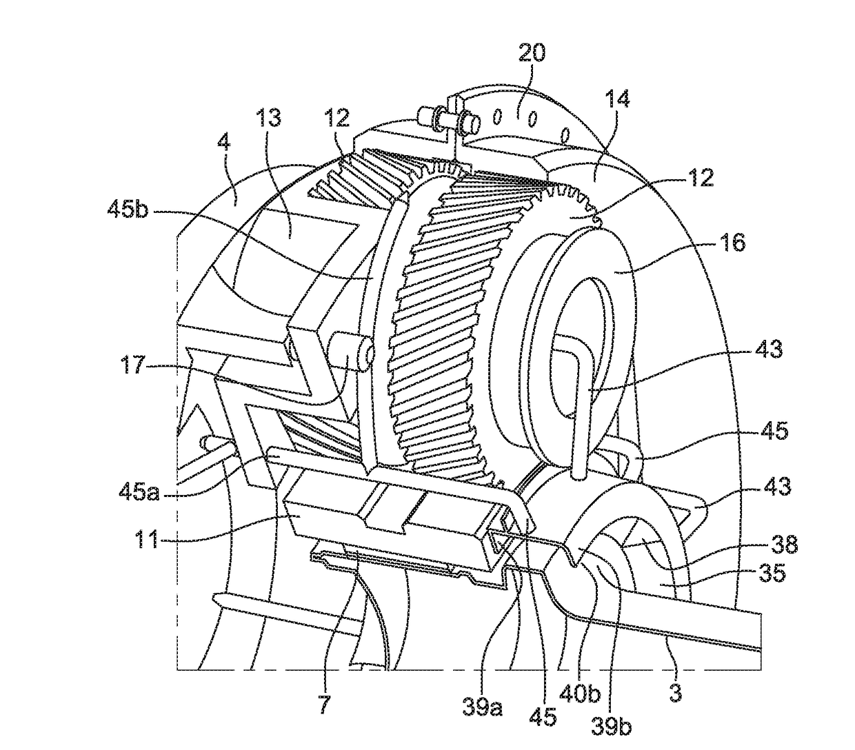
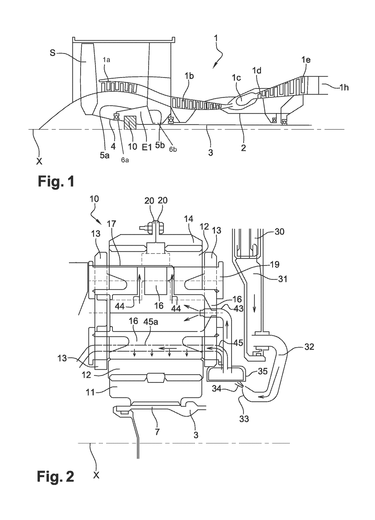
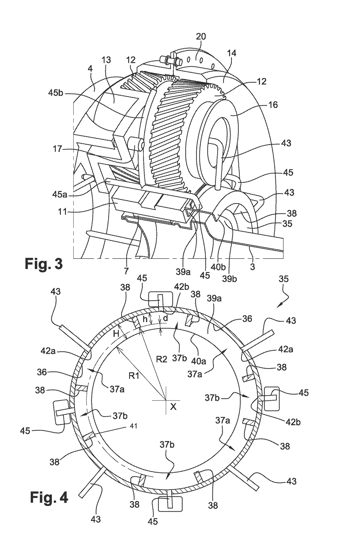
[0010]For this purpose, the invention relates to a bowl intended to supply oil to at least two oil distribution circuits connected to a planet carrier of an epicyclic reduction gear train, said planet carrier being in rotation, with the oil coming from a fixed means of oil ejection, said bowl being configured to be integral with said planet carrier and having an approximately cylindrical shape, being open radially inwards relative to an axis, characterized in that it is divided into a circumferential succession of separate cups, each arranged to communicate with one of said oil distribution circuits.

[0011]In other words, circumferential separations are placed between the successive cups on the circumference of the bowl. By separating the bowl into a circumferential succession of cups associated with the various oil distribution circuits, it is possible to distribute the flow rates among these circuits by acting on the circumferential extension of the cups. This offers an economical ...


PUM


Abstract

A bowl for supplying oil to at least two oil-distribution circuits which are connected to a planet carrier of an epicyclic reduction gearbox, the planet carrier rotating and the oil coming from a fixed oil ejector, the bowl being designed to be secured to the planet carrier and having a substantially cylindrical shape and being open radially towards the inside with respect to an axis. The bowl is divided into a circumferential succession of separate cups each designed to communicate with one of the oil distribution circuits A reduction gearbox with its supply device and a method of operation in a turbomachine are also disclosed.

Description

TECHNICAL FIELD[0001]The field of the present invention is that of turbine engines and more particularly that of differential transmission systems in these turbine engines, notably epicyclic reduction gear trains.PRIOR ART[0002]Existing turbine engines, notably turbine engines comprising one or more fans blowing a secondary airflow, comprise a transmission system, called a reduction gear, for driving this or these fan(s) at the proper rotary speed from the shaft of the power turbine of the primary body of the engine.[0003]The operation of reduction gear trains, in particular on turbine engines with a blower fan with a high by-pass ratio, requires a particularly high oil flow rate, of the order of 6000 to 7000 litres per hour at take-off, to provide lubrication and cooling of the gears and bearings.[0004]The reduction gears used include epicyclic reduction gear trains, which have the advantage of offering high reduction ratios of the rotary speed with reduced overall dimensions. Howe...

Claims


Application Information

Patent Timeline
Patent Type & Authority Applications(United States)
IPC IPC(8): F01D25/18F02C7/06F02C7/36F02K3/04F16H57/04F16N7/36
CPCF01D25/18F02C7/06F02C7/36F02K3/04F16H57/0427F16H57/0479F16H57/0482F16N7/363F05D2260/40311Y02T50/60F16H57/04
Inventor GEDIN, PATRICEFERAUD, BENJAMIN
Owner SAFRAN TRANSMISSION SYST
Learn More