Inkjet printer
a printer and inkjet technology, applied in the field of inkjet printers, can solve the problems of insufficient overcoat effect, insufficient visual effect, insufficient effect,
- Summary
- Abstract
- Description
- Claims
- Application Information
AI Technical Summary
Benefits of technology
Problems solved by technology
Method used
Image
Examples
first preferred embodiment
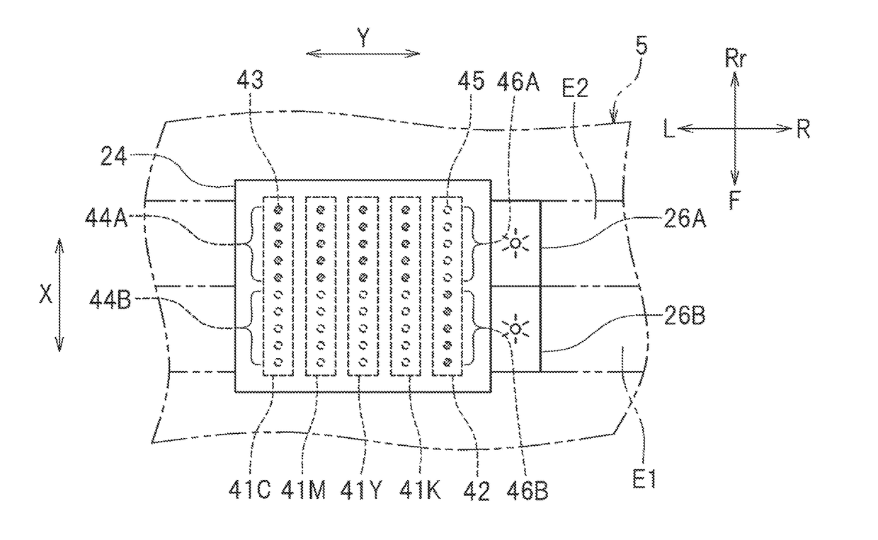
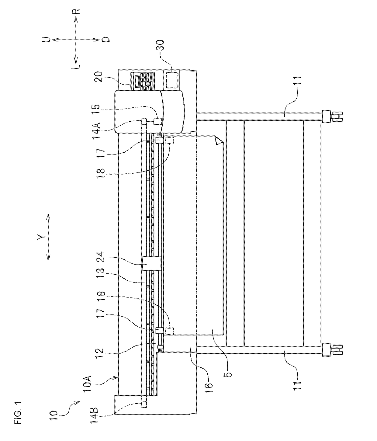
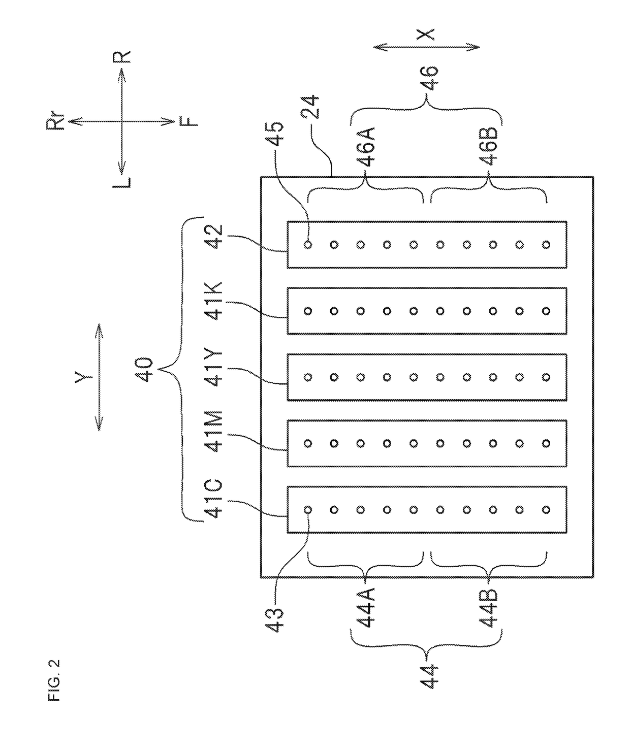
[0020]FIG. 1 is a front view of a wide-format inkjet printer (which is hereinafter referred to as “printer”) 10 according to a first preferred embodiment according to the present invention. FIG. 2 is a schematic diagram, illustrating the configuration of a surface (a bottom surface in this preferred embodiment) of a carriage 24 to be opposed to a recording medium 5. The printer 10 prints an image on a rolled recording medium 5 by moving the recording medium 5 sequentially forward (toward the downstream side in the sub-scanning direction X) and ejecting inks from ink heads 40 (refer to FIG. 2) that move in the main scanning direction Y.
[0021]The recording medium 5 is an object on which an image is printed. The recording medium 5 is not limited to particular media. The recording medium 5 may be a paper such as plain paper or inkjet printing paper, a transparent sheet such as one made from a resin or glass, or a sheet such as one made from a metal or rubber. In this preferred embodimen...
second preferred embodiment
[0057]A second preferred embodiment of the present invention is a preferred embodiment in which heaters are provided in place of the ultraviolet irradiators as ink curing units. Thus, the inks in the second preferred embodiment are inks that are cured by heat or inks that undergo accelerated curing when exposed to heat. The printer 10 according to the second preferred embodiment is identical with the printer 10 according to the first preferred embodiment except for having heaters in place of the ultraviolet irradiators and some differences in control. Thus, in the following description of the second preferred embodiment, the same members as those of the first preferred embodiment are denoted by the same reference numerals or symbols and redundant description is omitted or simplified. This also applies to the description of a third preferred embodiment of the present invention.
[0058]FIG. 7 is a schematic diagram, as viewed from above, of the top of the platen 16. Above the platen 16,...
third preferred embodiment
[0065]A third preferred embodiment of the present invention is a preferred embodiment in which the dot size (dot volume) is changed between the process color inks and the special color ink. In the printer 10 according to the third preferred embodiment, a first actuator 47 is provided in each of the first ink heads 41C to 41K, and a second actuator 48 is provided in the second ink head 42. The first dot controller 33 is set to send a “first control signal” that causes the first actuators 47 to form ink dots with a “first volume,” and the second dot controller 34 is set to send a “second control signal” that causes the second actuator 48 to form ink dots with a “second volume” which is greater than the “first volume.” In other words, settings are made such that the dot size of the special color ink is larger than the dot size of the process color inks. Because the dots of the special color ink is formed larger in size than the dots of the process color inks, the image formed by the pr...
PUM
 Abstract
Description
Claims
Application Information
 - R&D
- Intellectual Property
- Life Sciences
- Materials
- Tech Scout
- Unparalleled Data Quality
- Higher Quality Content
- 60% Fewer Hallucinations
Browse by: Latest US Patents, China's latest patents, Technical Efficacy Thesaurus, Application Domain, Technology Topic, Popular Technical Reports.
© 2025 PatSnap. All rights reserved.Legal|Privacy policy|Modern Slavery Act Transparency Statement|Sitemap|About US| Contact US: help@patsnap.com


