
Method for measuring field size factor for radiation treatment planning using proton pencil beam scanning

Active Publication Date: 2018-09-13
MAYO FOUND FOR MEDICAL EDUCATION & RES
View PDF0 Cites 15 Cited by
  • Summary
  • Abstract
  • Description
  • Claims
  • Application Information

AI Technical Summary

Benefits of technology

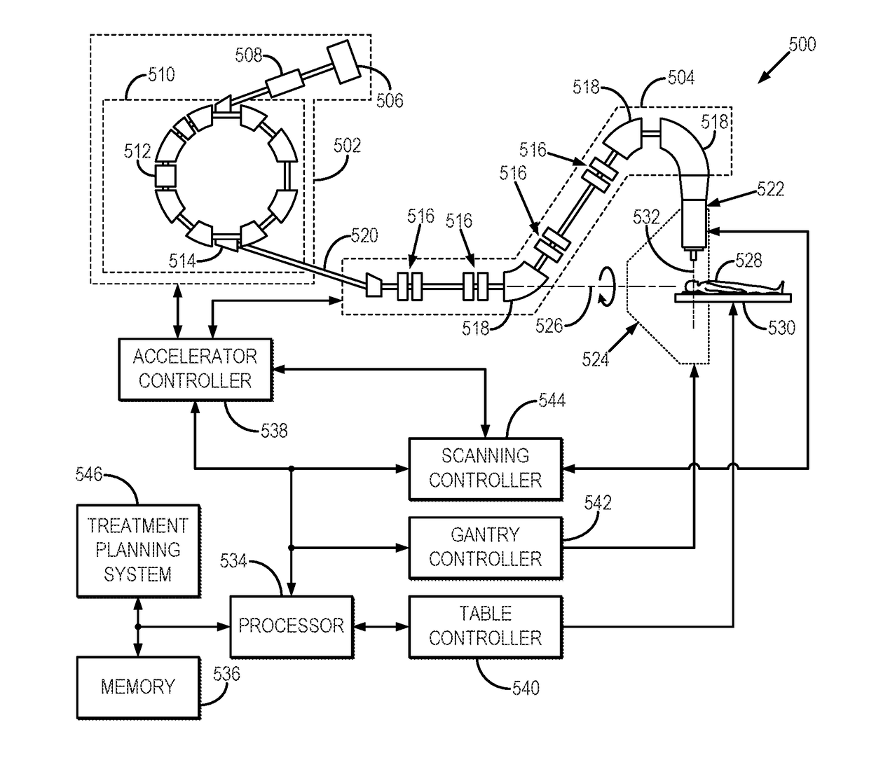
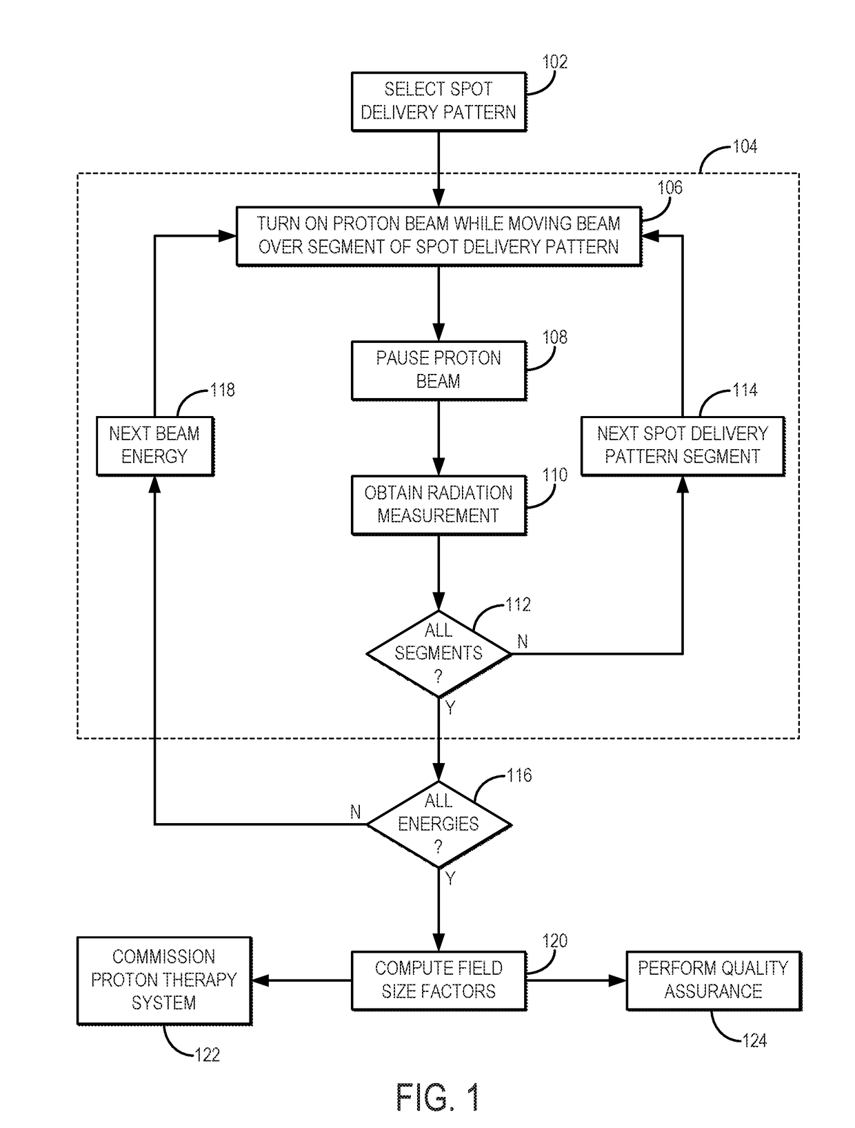
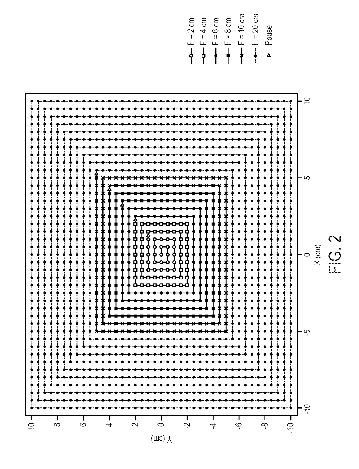
The present patent describes a method and system for quantifying the output of a proton therapy system. The system uses a computer system to generate control instructions for the proton therapy system, which define a spot delivery pattern through which a proton beam is moved. Each field size is associated with a different control point, which defines a pause time for the proton beam. A gradual spiral pattern is created that begins at the center of the field and ends at the edge. During each pause time, a radiation measurement is acquired, which is used to compute a field size factor for each field size. The output of the proton therapy system is then quantified based on these field size factors. The system includes a controller that receives these instructions and controls the operation of the proton therapy system accordingly. The technical effect is an improved method for accurately measuring the treatment output of proton therapy systems.

Problems solved by technology

Due to technical challenges, current clinical PBS systems cannot provide protons with energies below 70 MeV.
This limits the ability to treat shallow tumors (e.g., tumors at a depth less than 4 cm) unless a range shifter (“RS”) is added at the end of the nozzle.
The modeling process for a RS in a TPS is further complicated by spot size enlargement and the associated low-dose tails.
The process of commissioning a proton therapy system, or performing routine quality assurance on such a system, can also be time consuming.

Method used


Image

  • Method for measuring field size factor for radiation treatment planning using proton pencil beam scanning
  • Method for measuring field size factor for radiation treatment planning using proton pencil beam scanning
  • Method for measuring field size factor for radiation treatment planning using proton pencil beam scanning

Examples


Embodiment Construction

[0014]Described here are systems and methods for radiation treatment planning in proton therapy using pencil beam scanning (“PBS”). More particularly, the systems and methods described in the present disclosure related to quantifying the output from a proton therapy system implementing PBS. The systems and methods described in the present disclosure can therefore be implemented when commissioning a new proton therapy system, or when performing quality assurance (“QA”) on a proton therapy system.

[0015]Using the techniques described in the present disclosure, field size factor (“FSF”) is computed for multiple different field sizes, and these FSFs are used to characterize proton fluence values that are used for commissioning a proton therapy system, or for performing QA on a proton therapy system already in use. In general, a spot delivery pattern is designed and implemented in such a way that the proton beamlets are delivered in a pattern during which the beam delivery is paused at a ...


PUM


Abstract

Systems and methods for radiation treatment planning in proton therapy using pencil beam scanning (“PBS”) are described. More particularly, the systems and methods described in the present disclosure related to quantifying the output from a proton therapy system implementing PBS. The systems and methods described in the present disclosure can therefore be implemented when commissioning a new proton therapy system, or when performing quality assurance (“QA”) on a proton therapy system. A spot delivery pattern that includes a spiral out pattern is used for beam delivery. A number of control points along the spot delivery pattern define a beam pause time during which delivery of the proton beam is paused. Radiation measurements are obtained at the control points and at the end of the spot delivery pattern, and these radiation measurements are used to compute field size factors for field sized associated with the segments of the spot delivery pattern.

Description

CROSS-REFERENCE TO RELATED APPLICATIONS[0001]This application claims the benefit of U.S. Provisional Patent Application Ser. No. 62 / 468,637, filed on Mar. 8, 2017, and entitled “Efficient Method to Measure the Field Size Factor or Out Put Factor for Proton Pencil Beam Scanning.”BACKGROUND[0002]Pencil beam scanning (“PBS”) techniques have gained more popularity in proton therapy centers because PBS has reduced neutron dose; no need for apertures and compensators; and intrinsically enables intensity modulated proton therapy (“IMPT”). Due to technical challenges, current clinical PBS systems cannot provide protons with energies below 70 MeV. This limits the ability to treat shallow tumors (e.g., tumors at a depth less than 4 cm) unless a range shifter (“RS”) is added at the end of the nozzle.[0003]The spot sizes of proton beamlets increase when a RS is used, and these increases in spot size are more pronounced for low proton energies. This increase in spot size is due to the scattering...

Claims


Application Information

Patent Timeline
IPC IPC(8): A61N5/10
CPCA61N5/1044A61N5/1075A61N5/1081A61N2005/1087A61N2005/1074A61N5/1043
Inventor SHEN, JIAJIAN
Owner MAYO FOUND FOR MEDICAL EDUCATION & RES
Learn More