Three-dimensional building apparatus and three-dimensional building method

a three-dimensional building and building technology, applied in the field of three-dimensional building apparatus and three-dimensional building method, can solve the problems of deterioration of affecting the quality of the three-dimensional object, so as to achieve sufficient adhesion

Inactive Publication Date: 2018-09-06
MIMAKI ENG
View PDF3 Cites 3 Cited by
  • Summary
  • Abstract
  • Description
  • Claims
  • Application Information

AI Technical Summary

Benefits of technology

This patent describes a three-dimensional building apparatus and method that can generate a three-dimensional object with sufficient adhesion between unit layers even when using a photocurable material with large cure shrinkage. The apparatus includes an emitter for emitting active beam light and a heater for heating the upper surface of the deposition structure. The heater helps to directly and effectively heat the upper surface before the active beam light is emitted, even when using a low temperature cure condition. The apparatus also includes a support member, such as a pedestal, between the three-dimensional object and the stage to improve adhesion. Additionally, the apparatus can save energy during the building process by controlling the temperature of the heater based on the curing properties of the model material and support material. The heater can be a warm air jetting part that prevents excessive heating of the upper surface. Overall, this technology allows for the generation of high-quality three-dimensional objects with strong adhesion between layers using photocurable materials.

Problems solved by technology

When a three-dimensional object is built directly on a work surface of a stage, the bottom surface of the workpiece may be deformed when removed from the stage, resulting in deterioration of quality of the three-dimensional object.
Specifically, the surface shape of the work surface may be transferred to the bottom surface, or the bottom surface sticking to the work surface may be partially lost.
Meanwhile, the unit layers may interfere with each other due to differences in building conditions of the three-dimensional object, and the curing properties may vary to a non-negligible degree.
In particular, differences in curing properties between the materials may cause distortion in the vicinity of the contact surface between the body of the object and the pedestal, and the adhesion of the body to the pedestal is likely to be reduced.
As a result, separation between the body and the pedestal may occur during the course of formation of the workpiece, thereby reducing the reproducibility of the building position on the upper layer side.

Method used


Image

  • Three-dimensional building apparatus and three-dimensional building method
  • Three-dimensional building apparatus and three-dimensional building method
  • Three-dimensional building apparatus and three-dimensional building method

Examples


first embodiment

[0030]10>

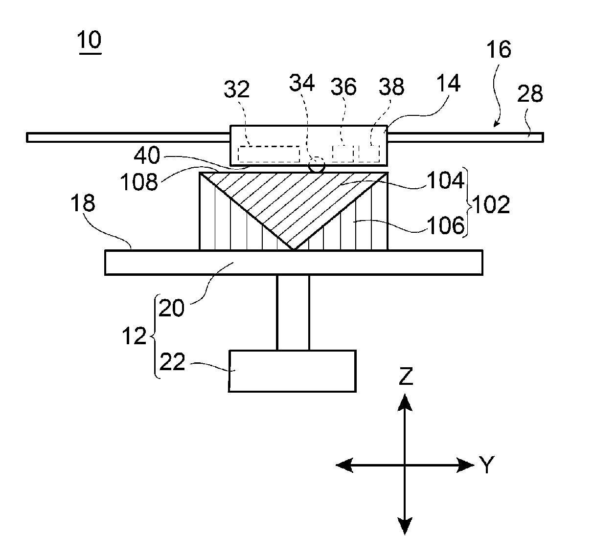
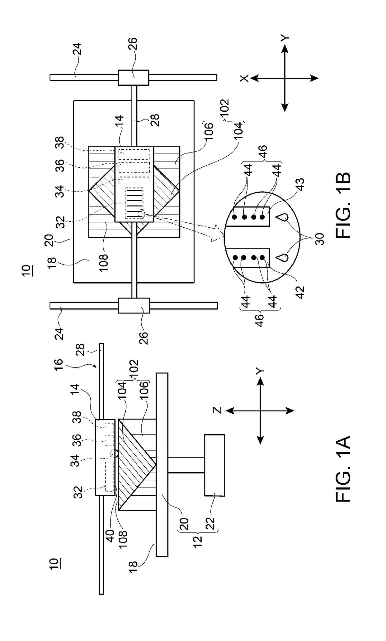
[0031]FIGS. 1A and 1B are schematic diagrams illustrating the main part of a three-dimensional building apparatus 10 according to a first embodiment. More specifically, FIG. 1A is a schematic side view of the three-dimensional building apparatus 10, and FIG. 1B is a schematic plan view of the three-dimensional building apparatus 10. The figures depict a deposition structure 102 that is a three-dimensional object 100 in the process of production.

[0032]The deposition structure 102 is formed with a model material 104 that is a raw material of the three-dimensional object 100 and a support material 106 that supports the model material 104 from the outside or the inside. More specifically, the deposition structure 102 is formed by successively depositing unit layers 131 to 134 (see FIG. 6) including the model material 104 and / or the support material 106 along the vertical direction.

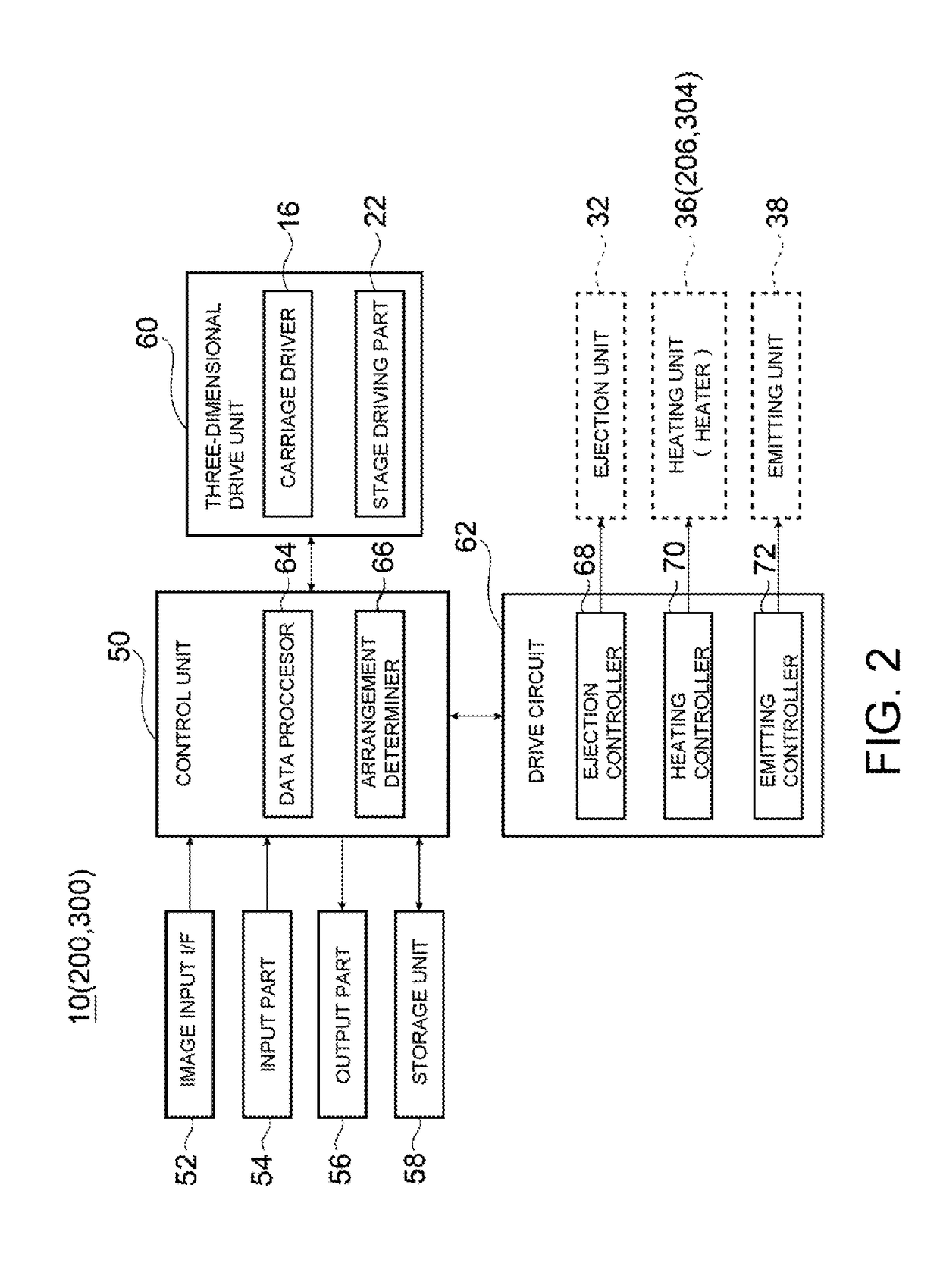
[0033]The three-dimensional building apparatus 10 includes a stage unit 12 on which the deposition...

second embodiment

[0087]A three-dimensional building apparatus 200 according to a second embodiment will be described with reference to FIGS. 7A and 7B. Like numerals are assigned to the same configurations or functions as those of the three-dimensional building apparatus 10 according to the first embodiment, and explanation thereof may be omitted.

[0088]200>

[0089]FIGS. 7A and 7B are schematic diagrams illustrating the principal part of the three-dimensional building apparatus 200 according to the second embodiment. More specifically, FIG. 7A is a schematic side view of the three-dimensional building apparatus 200, and FIG. 7B is a schematic plan view of the three-dimensional building apparatus 200.

[0090]The three-dimensional building apparatus 200 includes a carriage 202 that has a configuration different from that in the first embodiment (carriage 14 in FIG. 1). Specifically, the carriage 202 is mounted with a planarizing roller 204 (planarizer, heater) that planarizes the uppermost surface 108 of t...

third embodiment

Effect of Third Embodiment

[0103]As described above, the three-dimensional building apparatus 300 includes: [1] the stage 20; [2] the ejection unit 32; and [3] the emitting unit 38, and further includes [4] the external heater 304 that is arranged facing the work surface 18 of the stage 20 and heats the uppermost surface 108 of the deposition structure 102 in forming the workpiece 120. Even when this kind of configuration is employed, the three-dimensional object with sufficient adhesion between the unit layers 131 to 134 can be generated similarly to the first embodiment.

[0104][Remarks]

[0105]The present disclosure is not intended to be limited to the foregoing embodiments and can be modified as desired without departing from the scope of the disclosure, as a matter of course.

[0106]For example, although the first to third embodiments employ the configuration where the heating step (S44) is executed before the emitting step (S45), there is no restriction on the execution order of both...


PUM

PropertyMeasurementUnit
temperatureaaaaaaaaaa
photocurableaaaaaaaaaa

Abstract

To provide a three-dimensional building apparatus and a three-dimensional building method capable of generating a three-dimensional object with sufficient adhesion between unit layers even when a photocurable material having larger cure shrinkage due to photocuring placed under a low temperature condition is used as a model material and a support material. A three-dimensional building apparatus includes: a stage configured to hold a deposition structure formed by depositing unit layers; an ejector configured to eject a photocurable model material and a photocurable support material toward the uppermost surface of the deposition structure while moving relative to the stage; an emitter configured to emit an active beam light capable of curing the photocurable model material and the photocurable support material; and a heater configured to heat the uppermost surface of the deposition structure in forming a workpiece.

Description

CROSS REFERENCE TO RELATED APPLICATIONS[0001]This application claims the priority benefit of Japanese Patent Application No. 2017-038648, filed on Mar. 1, 2017. The entirety of the above-mentioned patent application is hereby incorporated by reference herein and made a part of this specification.TECHNICAL FIELD[0002]The present disclosure relates to a three-dimensional building apparatus and a three-dimensional building method for generating a three-dimensional object formed of a photocurable model material, by removing a support member formed of a photocurable support material from a workpiece obtained by successively depositing unit layers including the model material and / or the support material.BACKGROUND ART[0003]Three-dimensional building apparatuses (called 3D printers) have recently been developed, which generate an object having a three-dimensional shape by successively depositing layers in units of slices (hereinafter referred to as unit layers) along the vertical direction...

Claims


Application Information

Patent Timeline
Patent Type & Authority Applications(United States)
IPC IPC(8): B29C64/112B29C64/295B29C64/218B29C64/40B33Y10/00B33Y30/00
CPCB29C64/112B29C64/295B29C64/218B29C64/40B33Y10/00B33Y30/00
Inventor MUGISHIMA, HIKARUOCHI, KAZUHIRO
Owner MIMAKI ENG
Why Eureka
Try Eureka