
Sowing coulter arrangement of an agricultural machine

a technology of coulter and agricultural machine, which is applied in the direction of agricultural machines, furrow making/covering, agricultural tools and machines, etc., can solve the problems high-maintenance sowing coulters, and only limited application of double-disk coulters. , to achieve the effect of high-maintenance sowing coulters

Active Publication Date: 2018-09-06
HORSCH MASCHEN
View PDF5 Cites 15 Cited by
  • Summary
  • Abstract
  • Description
  • Claims
  • Application Information

AI Technical Summary

Benefits of technology

The present invention relates to a method for achieving a constant and precise distribution of seeds during planting. This is particularly useful for single-disk coulters, which are used for direct drilling in unprepared soil. By connecting the seed tube and catching element to the coulter frame or agricultural machine via a parallelogram linkage, changes in the angle position of the coulter no longer affect the position between the seed tube and catching element, resulting in improved distribution precision. Additionally, this method allows for the use of a metering device in a single-disk coulter and ensures consistent distribution quality during planting.

Problems solved by technology

Such parallelogram linkages, however, require an elaborate and costly input of parts.
In addition, each of the parallelogram linkages has very many pivot points, resulting in very high-maintenance sowing coulters.
Furthermore, such double-disk coulters are only suitable to a limited extent for direct drilling in particular, since great forces are required for the two cutting disks to penetrate into the soil.
It is not yet possible, however, to mount a metering device for single-grain metering on such sowing coulters with a central pivot point.
Particularly the angle positions are greatly influenced in this context so that precise seed placement cannot be ensured with different sowing depths.

Method used


Image

  • Sowing coulter arrangement of an agricultural machine
  • Sowing coulter arrangement of an agricultural machine
  • Sowing coulter arrangement of an agricultural machine

Examples


Embodiment Construction

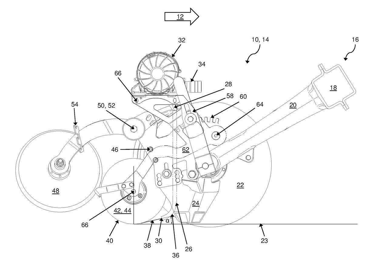
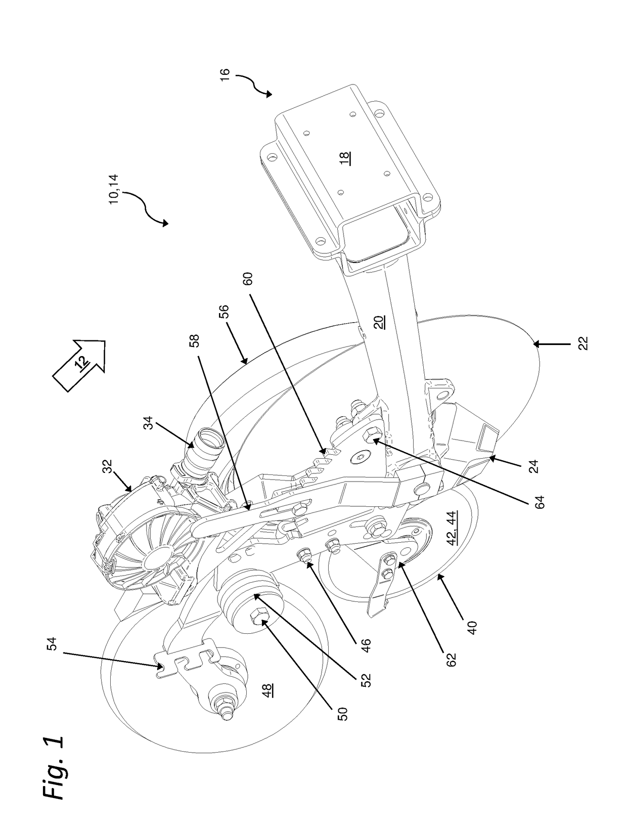
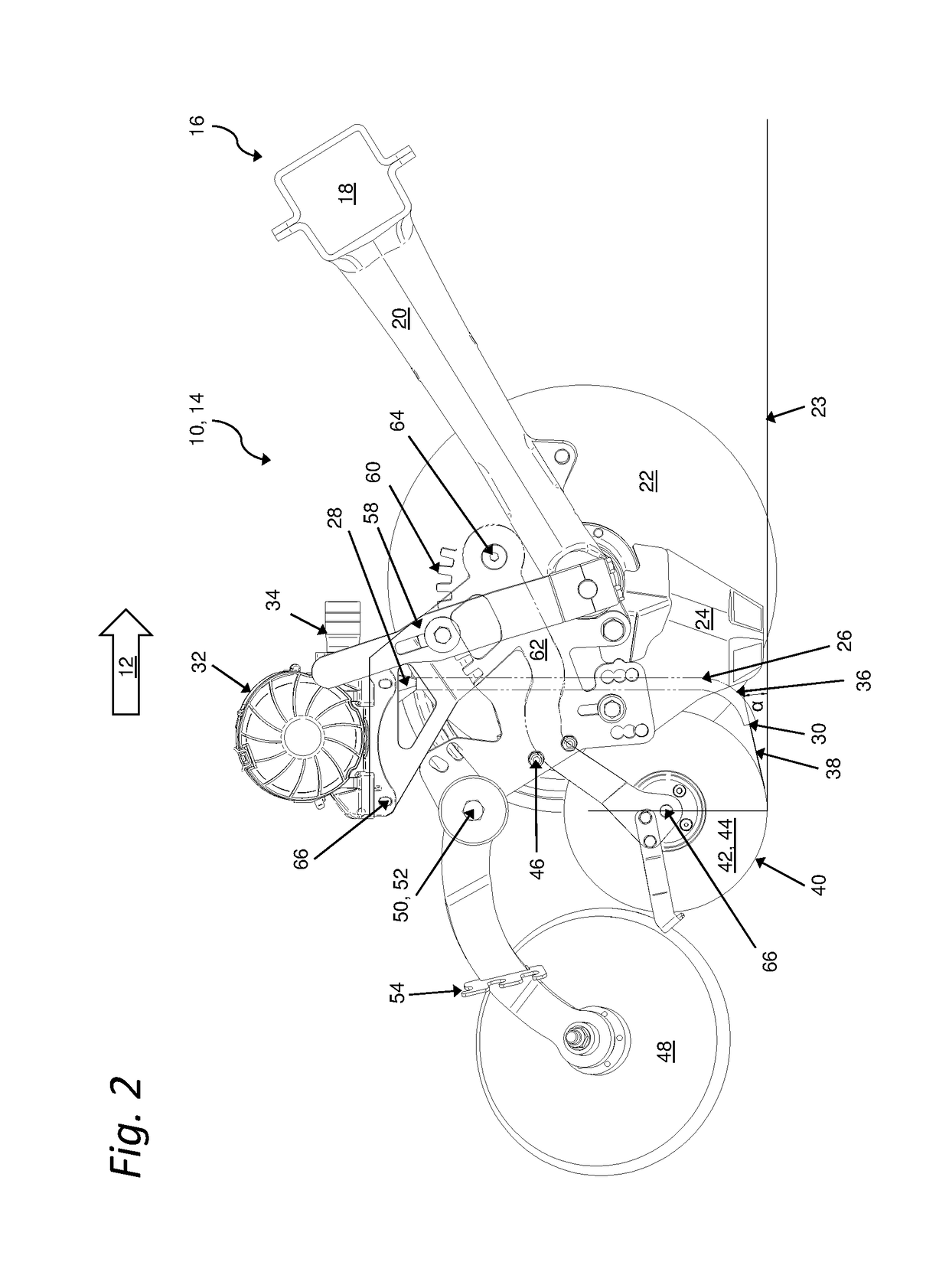
[0036]The same or equivalent elements of the invention are each designated by the same reference characters in the FIGS. 1 to 4e. Furthermore, and for the sake of clarity, only the reference characters relevant for describing the individual figures are provided. It should be understood that the detailed description and specific examples of the sowing coulter according to the invention, while indicating preferred embodiments, are intended for purposes of illustration only and are not intended to limit the scope of the invention.

[0037]FIG. 1 shows an embodiment variant of a sowing coulter arrangement 10 according to the invention in a schematic perspective view, which sowing coulter arrangement 10 can be used, for example, with an agricultural machine for spreading agricultural materials to be distributed, such as seeds, fertilizer, or the like. FIG. 2 shows the identical embodiment of the sowing coulter arrangement 10 according to FIG. 1 in a side view. In each case, the sowing coult...


PUM


Abstract

Disclosed is a sowing coulter arrangement comprising a suspension device for mounting the sowing coulter arrangement on a machine frame; a coulter frame connected to the suspension device for mounting components of the sowing coulter arrangement thereon; and a coulter disk. The arrangement further comprises a furrow closer pivotally mounted on the coulter frame; a metering device for dispensing the material to be distributed; a seed tube for transporting the material to be distributed from the metering device to a seed furrow; and a catching element for catching the material disposed downstream of the outlet of the seed tube. The metering device, the seed tube, and the catching element form a unit and are mounted on a carrier that is pivotably affixed to the coulter frame, whereby an arrangement of an outlet of a seed tube in relation to a catching element is at all times kept largely constant.

Description

CROSS-REFERENCE TO RELATED APPLICATION[0001]This application claims priority from German patent application No. 102015114362.3 filed Aug. 28, 2015, the disclosure of which is hereby incorporated herein in its entirety by reference.FIELD OF THE INVENTION[0002]The present invention relates to a sowing coulter arrangement of an agricultural machine for soil tillage and / or for spreading materials to be distributed, such as seeds, fertilizer, or the like.BACKGROUND[0003]Seed drill coulters or sowing coulters, such as double-disk coulters, single-disk coulters, or tine coulters, are known from the prior art in the most diverse of embodiment forms. Such a sowing coulter is disclosed in EP 2 022 307 B1, for example. The disclosed sowing coulter is used with an agricultural single-grain sowing machine. Arranged at a coulter frame, there is at least one coulter disk to serve as furrow-opening unit and therebehind is a seed tube with an associated catching roller and a subsequent pressure roll...

Claims


Application Information

Patent Timeline
Patent Type & Authority Applications(United States)
IPC IPC(8): A01B49/06A01B15/18A01B61/04A01C7/12A01C7/08A01B21/08A01C5/06A01C7/16A01C7/20
CPCA01B49/06A01B15/18A01B61/046A01C7/127A01C7/081A01B21/08A01C5/064A01C5/062A01C5/068A01C7/12A01C7/166A01C7/206A01C7/203A01C7/201
Inventor HORSCH, PHILIPP
Owner HORSCH MASCHEN
Learn More