Gas turbine engine arrangement

a technology of gas turbine engines and engine shafts, applied in the direction of engine components, machines/engines, engine fuctions, etc., can solve the problems of overly stressing the engine, unobstructed flow to the core, and increased lp shaft speed, so as to avoid sudden changes in the curvature of the streamline, the total pressure of the fan inlet is increased.

Active Publication Date: 2018-08-30
ROLLS ROYCE PLC
View PDF0 Cites 3 Cited by
  • Summary
  • Abstract
  • Description
  • Claims
  • Application Information

AI Technical Summary

Benefits of technology

The patent describes an invention that provides a porous grid in the fan duct to reduce fan inlet pressure and allow for higher rotational speeds of the fan and related components. This results in increased core flows and reduced mechanical load on the engine. The invention also includes an inlet screen with two different levels of porosity to minimize mixing of low and high total pressure streams and achieve a smooth airflow into the core. Overall, the invention improves engine performance and allows for more efficient testing with a given power output.

Problems solved by technology

Consequently, in order to perform this at Sea Level conditions, i.e. conditions different to the in-flight conditions, the LP shaft speed is increased, which may require unrepresentatively higher core power and which may in turn overly stress the engine.
Meanwhile, flow to the core is unobstructed, permitting high core flows, and so undisturbed high core power.

Method used


Image

  • Gas turbine engine arrangement
  • Gas turbine engine arrangement
  • Gas turbine engine arrangement

Examples


Embodiment Construction

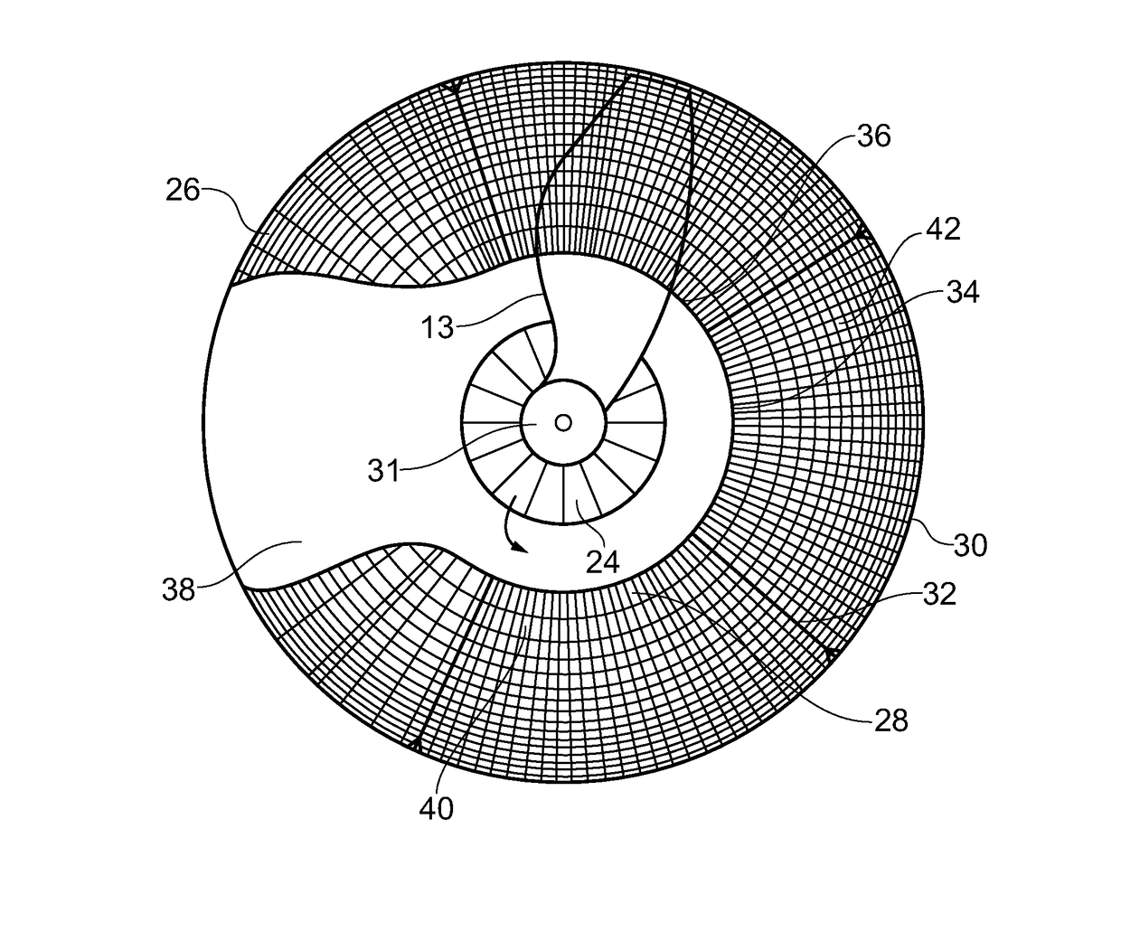
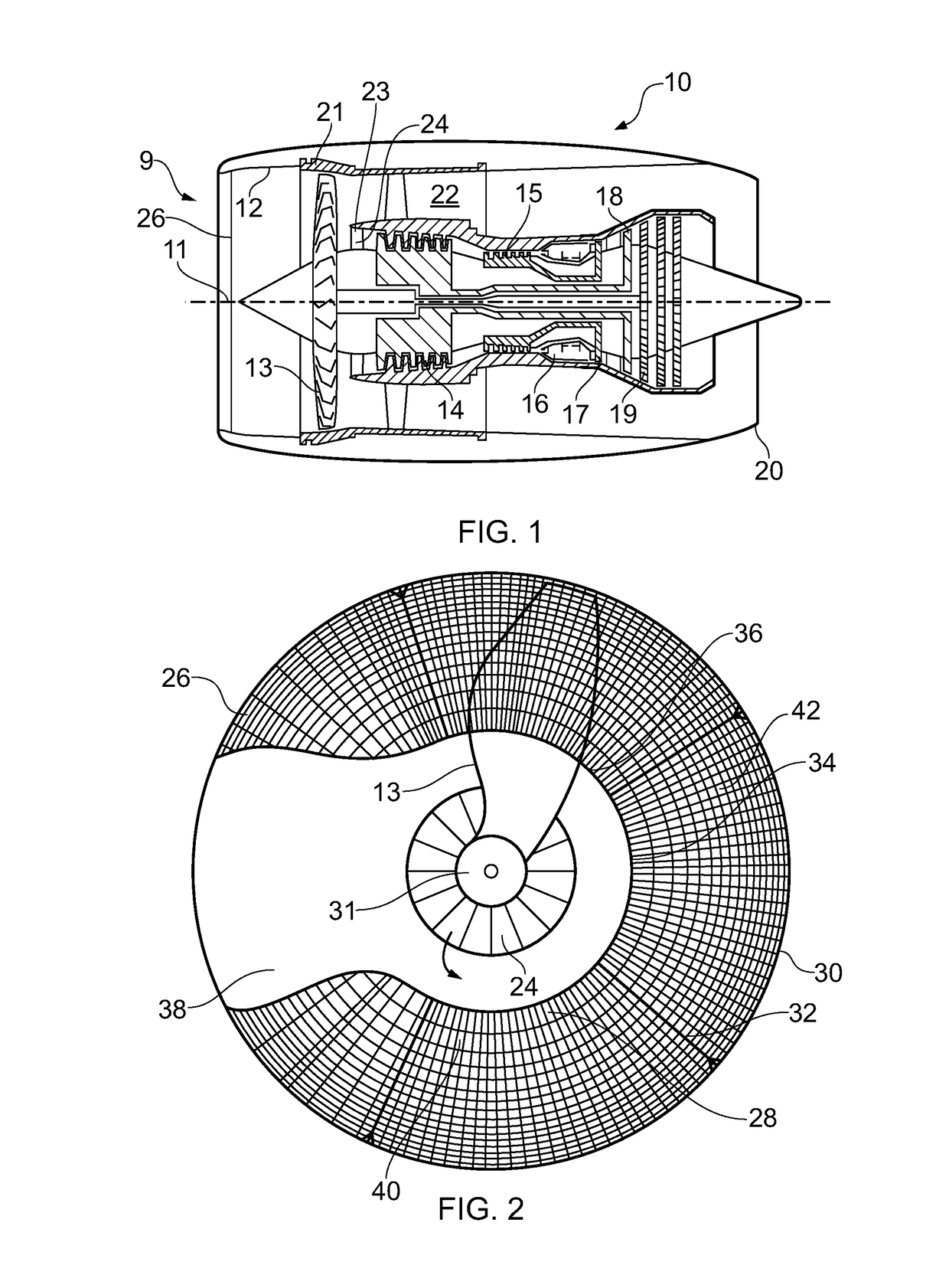
[0021]With reference to FIG. 1, a gas turbine engine arrangement is generally indicated at 10 comprising a gas turbine engine 9 having a principal and rotational axis 11. The engine 10 comprises, in axial flow series, an air intake 12, a propulsive fan 13, an intermediate pressure compressor 14, a high-pressure compressor 15, combustion equipment 16, a high-pressure turbine 17, an intermediate pressure turbine 18, a low-pressure turbine 19 and an exhaust nozzle 20. A fan casing 21 generally surrounds the engine 10 and defines the intake 12.

[0022]The gas turbine engine 10 works in the conventional manner so that air entering the intake 12 is accelerated by the fan 13 to produce two air flows: a first air flow into the intermediate pressure compressor 14 and a second air flow which passes through a bypass duct 22 to provide propulsive thrust. The intermediate pressure compressor 14 compresses the air flow directed into it before delivering that air to the high pressure compressor 15 w...


PUM


Abstract

A gas turbine engine arrangement comprising a gas turbine engine and an inlet screen. The gas turbine engine comprises an engine core comprising an inlet having a radial extent extending from an engine longitudinal axis to a first radial position, and a fan duct comprising an inlet having a radial extent extending from the first radial position to a fan casing, the inlet screen comprising an at least part annular porous grid radially extending across at least part of the radial extent of the fan duct inlet, and not extending across any substantial part of the radial extent of the core inlet.

Description

CROSS-REFERENCE TO RELATED APPLICATION[0001]This application is based upon and claims the benefit of priority from Greek Patent Application No. 20170100025 filed 24 Jan. 2017, the entire contents of which are incorporated herein.BACKGROUND1. Field of the Disclosure[0002]The present disclosure concerns an arrangement comprising an inlet screen for a ducted fan gas turbine engine.2. Description of the Related Art[0003]Ducted fan gas turbine engines comprise an engine core, comprising a compressor, combustor and turbine, and a ducted fan, which directs air to the core and to a bypass duct. Prior to entry into service, an aircraft gas turbine engine must be tested to confirm that it complies with various regulatory requirements. Some of these tests involve reaching or exceeding fan and / or low pressure (LP) turbine redline speed for reasons of testing bird ingestion for the fan, or investigating mechanical response for the components on the LP shaft. Consequently, in order to perform thi...

Claims


Application Information

Patent Timeline
Patent Type & Authority Applications(United States)
IPC IPC(8): F02C7/055F02K3/06
CPCF02C7/055F02K3/06F05D2220/32F05D2260/83F01D25/285
Inventor KYRITSIS, VASILEIOS
Owner ROLLS ROYCE PLC
Why Eureka
Try Eureka