Sensor system and method of collecting data

a technology applied in the field of sensor system and data collection method, can solve the problems of reducing the number of data packets per communication packet, and preventing congestion on the communication path

Active Publication Date: 2018-08-23
HITACHI LTD
View PDF2 Cites 10 Cited by
  • Summary
  • Abstract
  • Description
  • Claims
  • Application Information

AI Technical Summary

Benefits of technology

This patent is about a system to collect power consumption data from meters and use it to adjust the power supply to match demand fluctuations. However, if there are a large number of meters transmitting data simultaneously, the network can become congested and communication may fail. To prevent this, the system calculates the difference in power consumption per unit time on each meter and transmits data only when there is a significant difference. This reduces the amount of data transmitted and improves communication efficiency, preventing congestion on the network. Additionally, the system divides the communication packets into two groups: one with time information and sensor data, and another with the actual data measured by the sensors. This further reduces the amount of data transmitted and improves communication efficiency, preventing congestion on the network.

Problems solved by technology

However, when there are a very large number of meters on a network and the communicators of all the meters communicate all at once, the communication band of the network can become tight, causing congestion and rendering communication impossible, or the server load can increase, causing a substantial deterioration in the communication efficiency.
The data to be prioritized depends on the analysis purpose and the analysis result, and hence it is not possible to unilaterally determine on the terminal side whether data can be transmitted or received.
Further, the information acquired by the meter is basically a single type of data, for example, power consumption, and a plurality of types of sensor data are not handled on one terminal.

Method used


Image

  • Sensor system and method of collecting data
  • Sensor system and method of collecting data
  • Sensor system and method of collecting data

Examples


Embodiment Construction

[0025]An embodiment of this invention is now described with reference to the drawings.

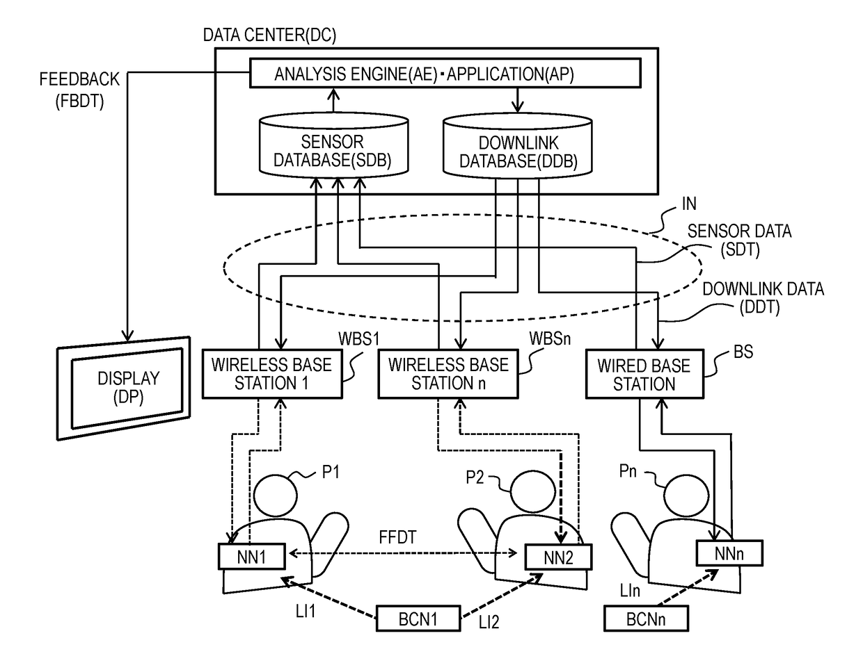
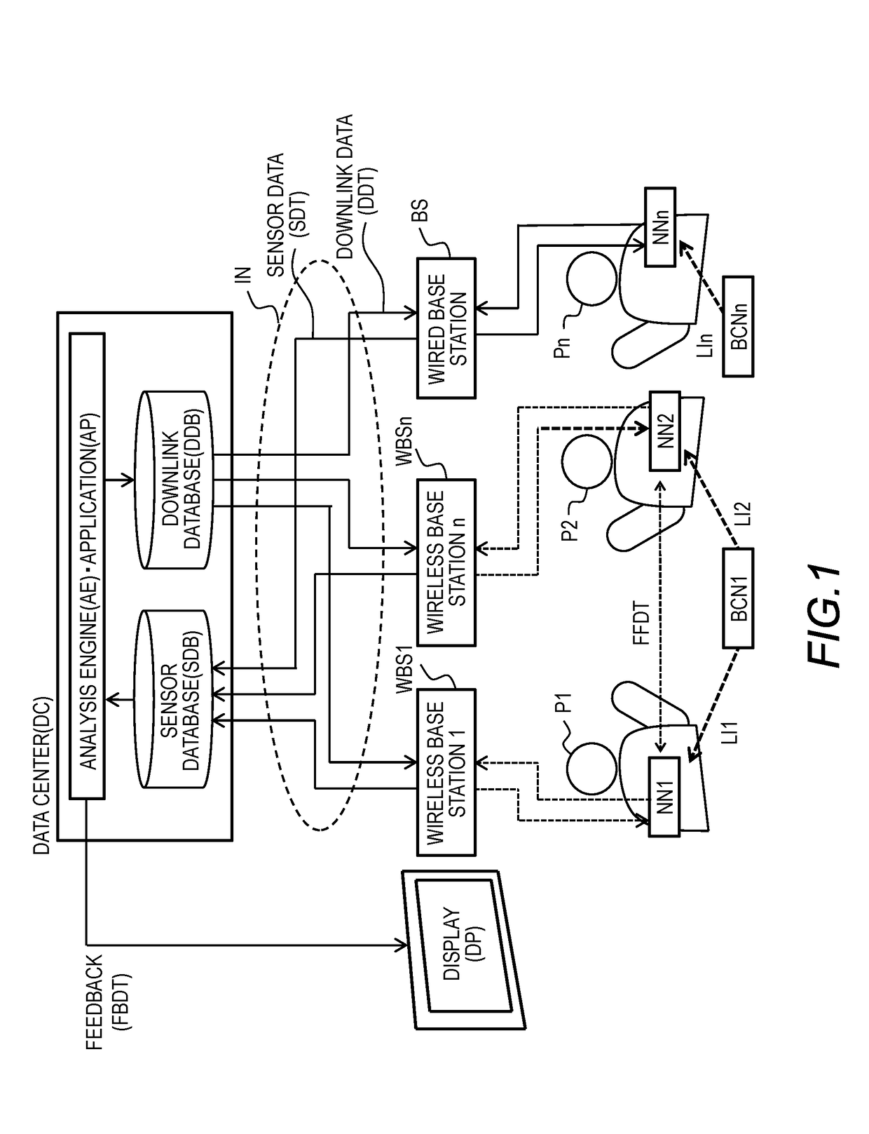
[0026]In order to clarify the concept and functions of this invention, first, a sensor system according to one embodiment of this invention is described. The sensor system according to one embodiment of the invention is a system to be used in order to help improve an organization by combining the behavior and surrounding situation of people wearing a nameplate-type sensor terminal acquired by the nameplate-type sensor terminal with face-to-face information of the wearers, and analyzing and illustrating, as organization activities, wearer's behavior, relations between the wearers, and a current organization evaluation (performance).

[0027]Another purpose of the sensor system is to improve work efficiency in a work field in which person-to-person communication in an organization, such as an on-site shop or medical facility, is strongly related with performance, by visualizing and analyzing flow lines ...


PUM


Abstract

Provided is a sensor system provided with: a terminal apparatus that has a sensor; and a base station that communicates with the terminal apparatus. The terminal apparatus stores acquisition frequency of a measurement data set to be transmitted to the base station, in measurement data sets of the sensor, and transmits first data that includes a reference time of an acquisition period of the measurement data sets of the sensor and the acquisition frequency, and second data that corresponds to the first data and that includes multiple measurement data sets, of the sensor, which have been acquired at the acquisition frequency in the acquisition period. The base station identifies the acquisition time of each of the measurement data sets included in the second data corresponding to the first data, on the basis of the reference time and the acquisition frequency included in the first data.

Description

BACKGROUND OF THE INVENTION[0001]This invention relates to a system configured to collect data measured by a sensor terminal, analyze the collected data, and provide the analysis result as feedback.[0002]In place of the organization evaluation based on an individualistic and qualitative assessment as hitherto performed, there have been developed technologies for visualizing human behavior and communication in an organization by using sensor technology, and objectively evaluating the quality of a business process. The sensors used in this technology include an infrared communicator for detecting face-to-face communication, a three-axis acceleration sensor for measuring the movement of the body, a microphone for measuring the characteristics of speech uttered by a wearer, and a plurality of types of sensors for measuring a surrounding situation, such as a temperature sensor and an illuminance sensor. In order to simultaneously measure a large number of people not only in individual un...

Claims


Application Information

Patent Timeline
IPC IPC(8): H04Q9/02G06Q10/06
CPCH04Q9/02G06Q10/06398H04Q2209/40H04Q2209/826H04Q2209/84H04Q2209/88H04Q9/00
Inventor HAYAKAWA, MIKI
Owner HITACHI LTD
Why Eureka
Try Eureka