
Apparatus and method for use in the treatment of hammertoe

a technology of appendix and hammertoe, which is applied in the field of orthopaedics, can solve the problems of affecting the healing effect of patients with digital deformities. , to achieve the effect of promoting bone regeneration, strong and durable connection, and fast healing

Active Publication Date: 2018-08-16
NSPIRED IDEAS
View PDF10 Cites 6 Cited by
  • Summary
  • Abstract
  • Description
  • Claims
  • Application Information

AI Technical Summary

Benefits of technology

The current device has interlocking hook threads that provide sharp and efficient cutting edges for self-tapping into the host material. It also has repository spaces for collecting chips created in the tapping process. The opposing halves of the device create a clamping load that secures the bone pin immediately and permanently into the host material or bone. The interlocking external threads of the device mechanically join with the surrounding host material or bone segments when the two halves are assembled and tightened together. The unique design creates an instant interlocking threaded union with excellent load-bearing capabilities and resistance to bending and shearing loads. The device can be easily removed and reinstalled if needed.

Problems solved by technology

Patients with digital deformities often experience significant pain from structural abnormalities.
Although this type of surgical procedure has alleviated the discomfort of hammer toe and other abnormalities of the toe and finger joints for countless patients, the use of K-wire can result in the possible post-surgical misalignment of the phalanges (e.g., caused by distraction of the K-wire), as well as swelling, inflammation, and possible infection at the site of the exposed K-wire segment.
These devices are typically comprised of metallic or thermoplastic materials which, while being biocompatible, are also physiologically inert and thus are not resorbed by the body.
There are, however, conditions in which an arthrodesis, or fusing of the affected finger or toe joint is desired, making a permanent device which is designed to permit joint flexion / extension inappropriate.

Method used


Image

  • Apparatus and method for use in the treatment of hammertoe
  • Apparatus and method for use in the treatment of hammertoe
  • Apparatus and method for use in the treatment of hammertoe

Examples


Embodiment Construction

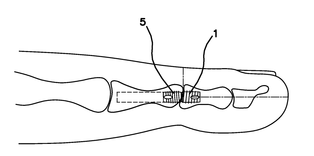
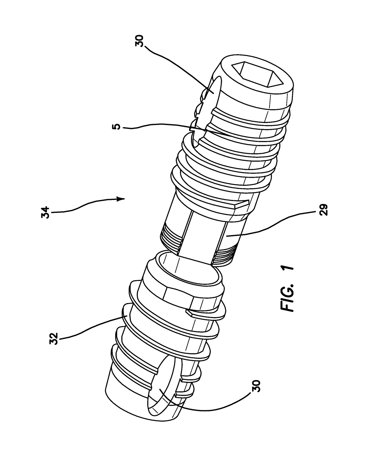
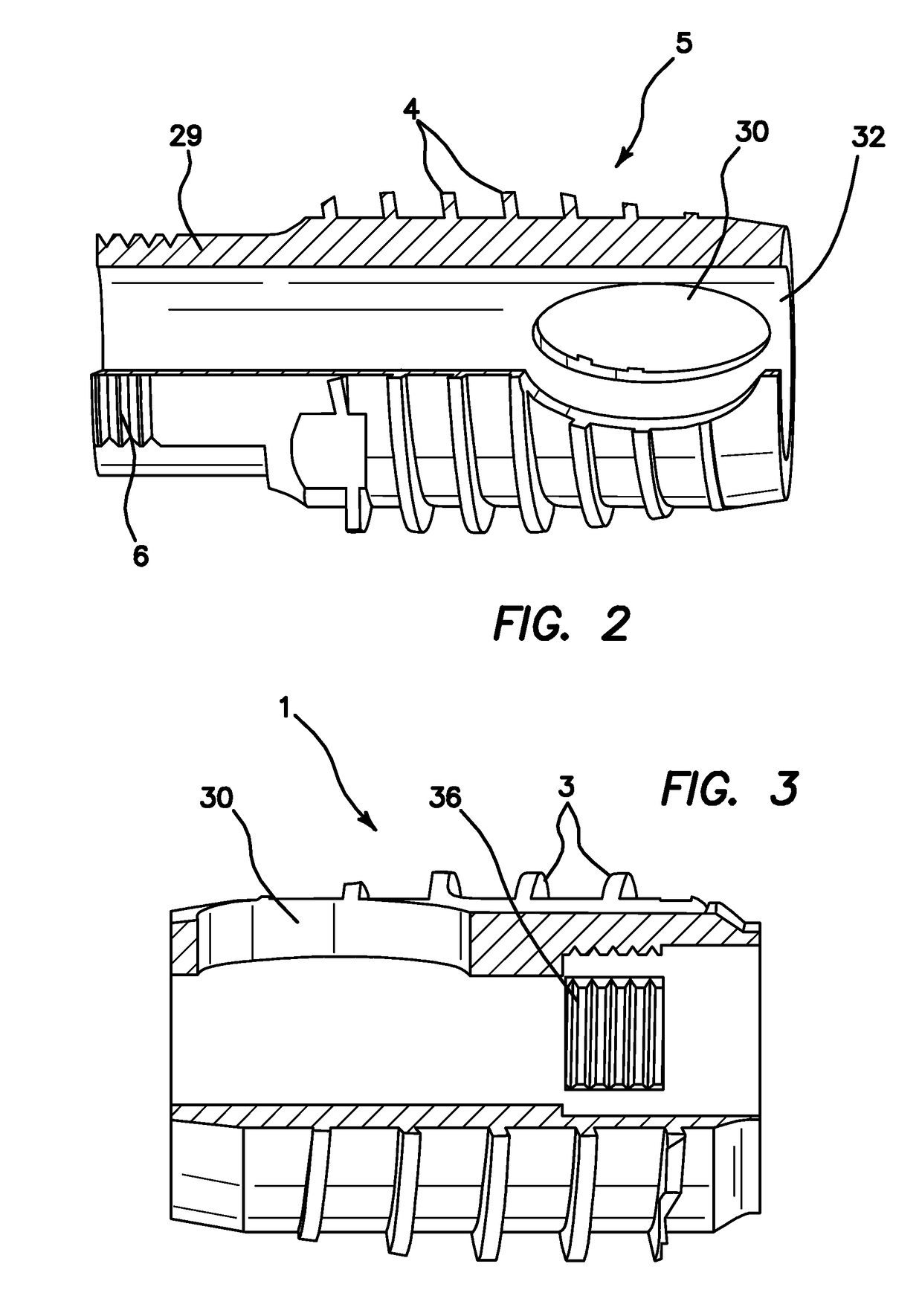
[0047]Turning now to FIG. 1, a distal half 1 and a proximal half 5 of the bone pin 34 are shown. As described below distal half 1 is implanted in the distal phlange and proximal half 5 is implanted into the proximal phlange of a hammer toe joint. Both halves 1, 5 are generally cylindrical with a longitudinal bore define therethrough on the longitudinal axis of each half. The distal half 1 includes an external helical thread 3 defined into the exterior surface of the distal half 1. The tooth 32 of the external helical thread 3 is defined between a minor diameter 8 and a major diameter 7. Similarly, an external helical thread 4 is also defined into the exterior surface of the proximal half 5, however the external thread 3 of the distal half 1 has a greater pitch than that of the threads 4 of the proximal half 5. The proximal half 5 further comprises a male peg 29 on its distal end. An external helical thread 6 is defined into the exterior surface of the male peg 29. A mating internal ...


PUM


Abstract

An orthopedic drill bit includes a cutting head formed to include diametrically opposed cutting lips leading to a central point and away to a radiused periphery to center said bit. The drill includes flutes extending from a cutting end, said flutes having a dulled periphery to prevent out of round holes. The flute design increases in width progressively from the tip up the shank, to maintain an adequate and unrestricted space for chips to easily move upward, preventing the chips from being compressed into a smaller opening while maintaining the tapered depth of the flutes for strength.

Description

CROSS-REFERENCE TO RELATED APPLICATIONS[0001]This is a continuation-in-part application of prior application Ser. No. 14 / 687,913, filed Apr. 16, 2015, which is a continuing application of Ser. No. 12 / 572,882 filed on Oct. 2, 2009, pursuant to 35 U.S.C. § 120 and 121, both prior applications hereby incorporated by reference in their entirety.BACKGROUND OF THE INVENTION1. Field of the Invention[0002]The invention relates to the field of orthopedics, and more particularly to a bone pin for the coupling of two separate pieces of bone together for use in the surgical correction of hammer toe.2. Description of the Prior Art[0003]One surgical method of treatment of hammer toe involves the surgical implantation of bone pins, and more particularly, an interphalangeal fusion pin which provides an anatomically correct angle between a first phalange and a second adjacent phalange, such as the proximal phalange and the intermediate phalange which exists at the proximal interphalangeal joint, whe...

Claims


Application Information

Patent Timeline
Patent Type & Authority Applications(United States)
IPC IPC(8): A61B17/72A61B17/86A61F2/42A61F2/30
CPCA61F2/4225A61B17/8685A61F2002/30772A61F2002/3085A61F2002/30235A61F2002/30622A61F2002/423A61B17/7291A61B17/7225A61F2230/0069A61F2220/0008A61F2002/30405A61F2002/30624A61F2002/30632A61F2002/30649A61F2002/4228
Inventor REED, GARY
Owner NSPIRED IDEAS
Learn More