
Distributed virtual network embedding

a distributed virtual network and network layer technology, applied in the field of network function virtualization, can solve the problems of high computational complexity, significant signaling overhead for a very large number of paths in a large-scale network, and high computational complexity in centralized systems

Active Publication Date: 2018-08-09
FUJITSU LTD
View PDF0 Cites 28 Cited by
  • Summary
  • Abstract
  • Description
  • Claims
  • Application Information

AI Technical Summary

Benefits of technology

The patent describes a method for embedding a virtual network request into a resource orchestration framework. The method involves receiving a virtual network request that specifies virtual nodes and links between them, and identifying a set of physical nodes that can host the virtual nodes. The physical nodes are then mapped to the virtual nodes and the request is divided into sub-requests to avoid overlapping virtual links. The method also includes computing chaining solutions for the sub-requests and combining them to generate the mapping solution. The technical effect of this invention is to efficiently allocate resources for virtual networks and optimize network performance.

Problems solved by technology

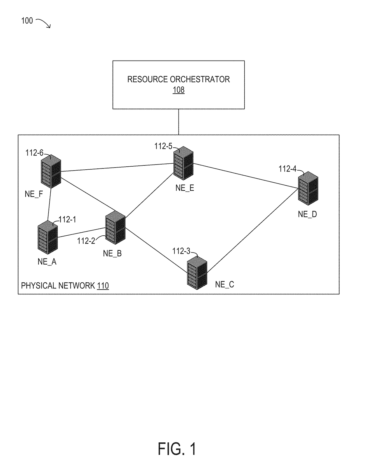
A hybrid architecture (e.g., one with geographically distributed orchestrators that replicate a global view of service functions, virtual machines, and networks) can lead to additional challenges, such as managing the global network state, maintaining the confidentiality of various network domains, and managing high computation complexity on a large-scale global view.
Furthermore, mapping a single virtual link would typically require signaling along all possible inter-domain paths, which can result in significant signaling overhead for a very large number of paths in a large-scale network.
Previously proposed virtual network mapping algorithms for directly mapping an entire virtual network request in a mesh topology have high computational complexity in centralized systems and also have high operational and signaling complexity of virtual node placement at domains and (for multi-domain cases) inter-domain paths between virtual nodes in distributed systems.

Method used


Image

  • Distributed virtual network embedding
  • Distributed virtual network embedding
  • Distributed virtual network embedding

Examples


Embodiment Construction

)

[0042]In the following description, details are set forth by way of example to facilitate discussion of the disclosed subject matter. It should be apparent to a person of ordinary skill in the field, however, that the disclosed embodiments are merely examples and are not exhaustive of all possible embodiments.

[0043]Throughout this disclosure, a hyphenated form of a reference numeral refers to a specific instance of an element and the un-hyphenated form of the reference numeral refers to the element generically or collectively. Thus, as an example (not shown in the drawings), widget “12-1” refers to an instance of a widget class, which may be referred to collectively as widgets “12” and any one of which may be referred to generically as a widget “12”. In the figures and the description, like numerals are intended to represent like elements.

[0044]As will be described herein, a distributed resource orchestration framework is disclosed that provides a scalable vertex-centric distribute...


PUM


Abstract

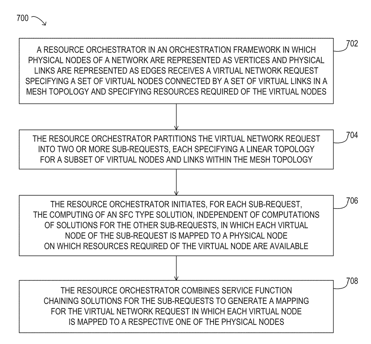
Systems and methods for performing distributed virtual network embedding are disclosed. A resource orchestrator may receive a virtual network request specifying a set of virtual nodes, a set of virtual links, each connecting two virtual nodes in a mesh topology, and resource requirements for some virtual nodes. The orchestrator may partition the virtual network request into multiple sub-requests, each specifying a linear topology for a subset of the virtual nodes and links within the mesh topology. The sub-requests may collectively include all virtual links within the mesh topology with no overlapping links. Resource orchestrators may collaborate to compute, independently for each sub-request, a respective chaining solution in which each virtual node is mapped to a physical node having resources sufficient to implementing the virtual node. A resource orchestrator may combine the respective chaining solutions for each of the sub-requests to generate a mapping solution for the virtual network request.

Description

BACKGROUNDField of the Disclosure[0001]The present disclosure relates generally to network function virtualization and, more particularly, to systems and methods for performing virtual network request embedding over arbitrary topologies using distributed resource orchestration.Description of the Related Art[0002]Emerging network applications, such as cloud and big data applications, may involve joint consideration of IT resources residing within multiple domains within one or more data centers (DCs). Network function virtualization (NFV) can be used to virtualize network functions and migrate them from devices that are built for a single, specific purpose to multi-purpose virtual machines, which may reduce service deployment costs and improve service flexibility. As more service functions move to virtual machines in geographically distributed data centers and as more individually-managed Networks-on-Demand are enabled by software defined networking (SDN) technology, end-to-end netwo...

Claims


Application Information

Patent Timeline
Patent Type & Authority Applications(United States)
IPC IPC(8): H04L12/915H04L12/713H04L12/931H04L12/24H04L12/911H04L45/586
CPCH04L47/785H04L45/586H04L47/827H04L41/12H04L41/0893H04L49/70H04L43/0852H04L43/0876H04L43/16H04L47/829H04L41/40H04L41/122H04L43/20
Inventor ZHANG, QIONGPALACHARLA, PAPARAOIKEUCHI, TADASHIWANG, XIKIM, INWOONG
Owner FUJITSU LTD
Learn More