Damper device

a technology of adamper and a spherical body, which is applied in the direction of machines/engines, liquid fuel feeders, and positive displacement liquid engines. it can solve the problems of reducing the durability affecting the performance of the welded parts, and affecting the welded parts. it is easy to avoid contact, prevent the occurrence of abnormal noise, and easy to handl

Active Publication Date: 2018-08-09
TOYOTA JIDOSHA KK +2
View PDF22 Cites 10 Cited by
  • Summary
  • Abstract
  • Description
  • Claims
  • Application Information

AI Technical Summary

Benefits of technology

[0010]According to the configuration described above, contact portions between the holder of the coupler and the first and second flexible portions forming the rim of the diaphragm damper are limited so that it is possible to easily avoid a contact between the holder and the rim at portions other than such contact portions. Therefore, even if the damper device vibrates, it is possible to prevent the occurrence of abnormal noise caused by a contact therebetween at portions other than such contact portions.
[0011]According to the above mentioned aspect, a plurality of the couplers is provided in a circumferential direction of the plurality of diaphragm dampers. According to the configuration described above, the configuration as one unit of the diaphragm dampers and the couplers is stabilized and thus is easy to handle, and therefore, it is possible to further improve the mounting efficiency of the diaphragm dampers.

Problems solved by technology

In the damper device including the plurality of diaphragm dampers as described above, when the diaphragm dampers are independently mounted to the high-pressure fuel pump, the number of mounting steps becomes large so that the mounting efficiency of the diaphragm dampers is difficult to improve.
However, when the peripheral portions of the diaphragm dampers are in contact with the coupler, there is a possibility that the durability of the welded portions may decrease due to rubbing caused by such contact.

Method used


Image

  • Damper device
  • Damper device
  • Damper device

Examples


Embodiment Construction

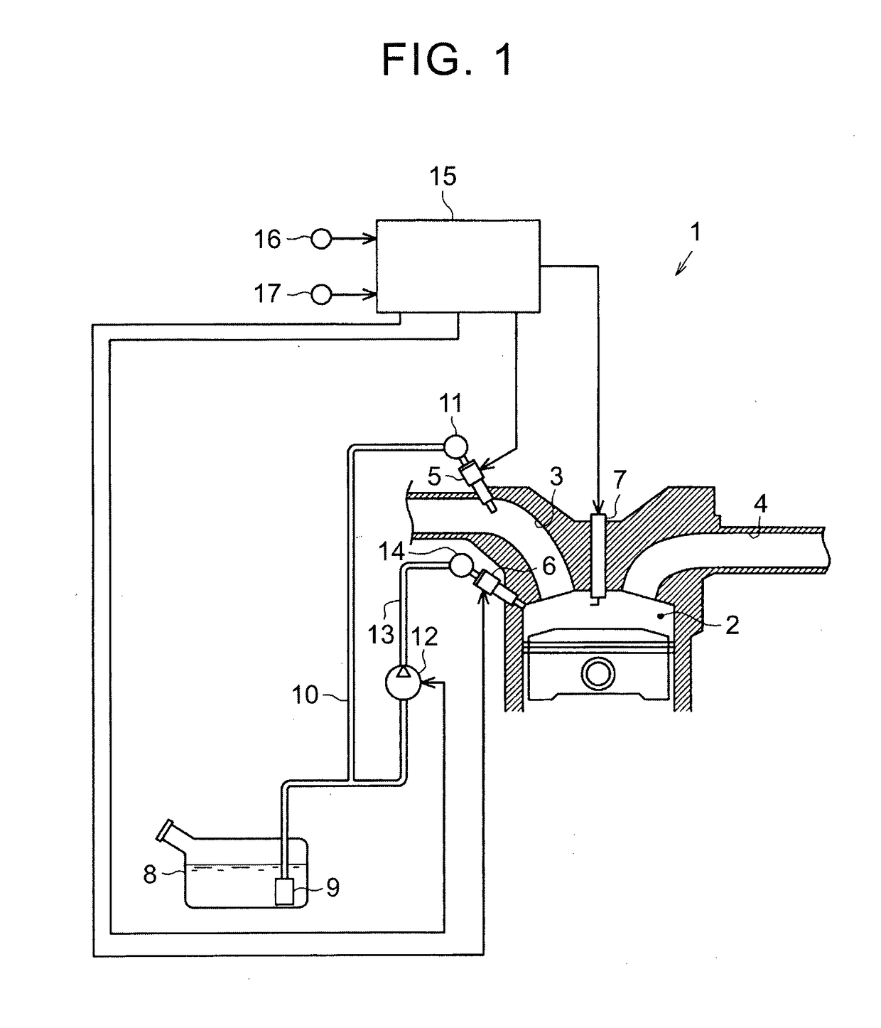
[0021]An embodiment of a damper device will be described with reference to FIG. 1 to FIG. 8. As shown in FIG. 1, an internal combustion engine 1 including the damper device has intake passages 3 and exhaust passages 4 that are connected to combustion chambers 2. A port injection valve 5 that injects fuel into the intake passage 3 is disposed in each intake passage 3. An in-cylinder injection valve 6 that injects fuel into the combustion chamber2 and a spark plug 7 are disposed in each combustion chamber 2.

[0022]The internal combustion engine 1 has a fuel tank 8 storing the fuel that is injected from the port injection valves 5 and the in-cylinder injection valves 6. The fuel tank 8 is provided therein with a feed pump 9 that pumps out the fuel stored in the fuel tank 8. A low-pressure fuel passage 10 is connected to the feed pump 9 and the port injection valves 5 are connected to the low-pressure fuel passage 10 via a low-pressure fuel pipe 11.

[0023]The low-pressure fuel passage 10 ...


PUM


Abstract

A damper device is provided in a flow passage of a fluid. The damper device includes a plurality of diaphragm dampers that are stacked together. Each of the plurality of diaphragm dampers includes a first flexible portion, a second flexible portion, and a rim including a welded portion. A peripheral edge of the first flexible portion and a peripheral edge of the second flexible portion are welded together in the welded portion. Each of the plurality of diaphragm dampers is configured to seal a gas in an inner region between the first flexible portion and the second flexible portion. A coupler that couples the plurality of diaphragm dampers together includes holders that hold the rims of the plurality of diaphragm dampers. A gap is provided between the holder of the coupler and the welded portion of each of the plurality of diaphragm dampers.

Description

BACKGROUND OF THE INVENTION1. Field of the Invention[0001]The invention relates to a damper device.2. Description of Related Art[0002]Japanese Patent Application Publication No. 2007-218264 (JP 2007-218264 A) discloses a damper device provided in a high-pressure fuel pump or the like. Two diaphragm dampers are disposed in a stacked state for preventing the pressure pulsation of fuel in the damper device. The damper device described in JP 2007-218264 A reduces the pressure pulsation of the fuel in the high-pressure fuel pump by bending of the diaphragm dampers according to the pressure of the fuel in the high-pressure fuel pump. Each diaphragm damper has a welded portion where the peripheral edges of two diaphragms are welded together and a gas is sealed in an inner region between the diaphragms. This damper device is configured such that a washer guide fixed to the high-pressure fuel pump is in contact with one side surface of the peripheral portion of each diaphragm damper. While a...

Claims


Application Information

Patent Timeline
Patent Type & Authority Applications(United States)
IPC IPC(8): F02M55/04F04B11/00
CPCF02M55/04F04B11/0016F02M2200/26F02M2200/315F02M37/0041
Inventor YABUUCHI, TAKEYUKISUGIMOTO, SHINICHIHISHINUMA, OSAMUYAMADA, HIROATSUIWA, TOSHIAKIOGAWA, YOSHIHIROSATO, YUSUKE
Owner TOYOTA JIDOSHA KK
Why Eureka
Try Eureka