
Exhaust Purifying Device and Working Vehicle

a technology for purifying devices and working vehicles, which is applied in mechanical equipment, machines/engines, electric control, etc., can solve the problems of shortening the working life and abrasion of the sliding surface between the bearing members, so as to reduce the abrasion of the valve body and prolong the working life of the throttle valv

Active Publication Date: 2018-08-09
KOMATSU LTD
View PDF3 Cites 1 Cited by
  • Summary
  • Abstract
  • Description
  • Claims
  • Application Information

AI Technical Summary

Benefits of technology

The invention relates to a valve controller for an engine that increases the opening of the throttle valve during acceleration and decreases it during deceleration. This reduces wear and tear on the valve, which increases its lifespan.

Problems solved by technology

However, a frequent control of the open degree by the exhaust throttle valve causes abrasion on sliding surfaces between a bearing member and a valve body in the exhaust throttle valve.
When the abrasion progresses, the exhaust throttle valve interferes with a housing to shorten a working lifetime.

Method used


Image

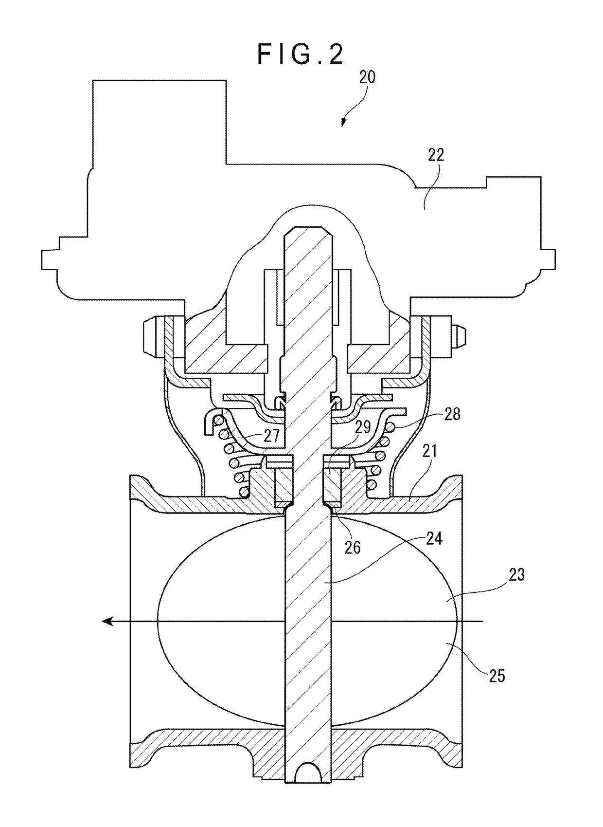
  • Exhaust Purifying Device and Working Vehicle
  • Exhaust Purifying Device and Working Vehicle
  • Exhaust Purifying Device and Working Vehicle

Examples


Embodiment Construction

)

[0019]Exemplary embodiment(s) of the invention will be described below with reference to the attached drawings.

[0020][1] Schematic Structure of Exhaust Purifying Device 10

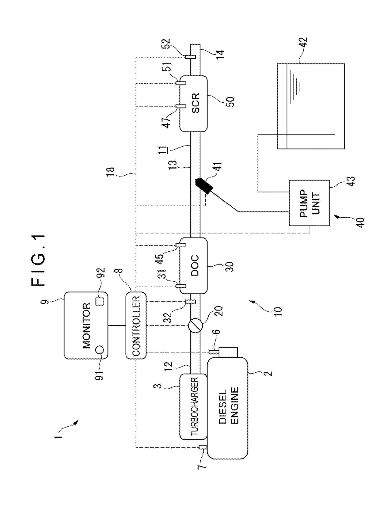
[0021]FIG. 1 schematically shows a structure of a working vehicle 1 in which an exhaust purifying device 10 according to an exemplary embodiment of the invention is mounted.

[0022]Herein, the working vehicle 1 is a machine configured to work for excavation, ground leveling and the like and to deliver earth and sand and the like, for instance, in a mine and a construction site of a road and the like. Examples of the working vehicle 1 include: a construction machine such as a wheel loader and a wheel type backhoe; and a delivery vehicle such as a forklift.

[0023]The working vehicle 1 includes: a diesel engine 2; a turbocharger 3 including a turbine and configured to rotate the turbine by an exhaust gas of the diesel engine 2 to compress air to be supplied to the diesel engine 2; a controller 8; a monitor 9; and an exh...


PUM


Abstract

An exhaust purifying device mounted in a working vehicle includes: an exhaust passage through which an exhaust gas discharged from an engine flows; a throttle valve configured to change a passage area of the exhaust passage; an exhaust aftertreatment device disposed downstream of the throttle valve; and a valve controller configured to control an open degree of the throttle valve. The valve controller is configured to control the open degree of the throttle valve to be larger in a low load region below a predetermined load range and in a high load region exceeding the predetermined load range than in a medium load region that is the predetermined load range.

Description

TECHNICAL FIELD[0001]The present invention relates to an exhaust purifying device and a working vehicle.BACKGROUND ART[0002]A working vehicle such as a wheel loader includes an exhaust aftertreatment device (e.g., a diesel oxidant catalyst (DOC) and a selective catalytic reduction (SCR)) provided in an exhaust passage of an engine, the exhaust aftertreatment device being configured to burn particulate matters (PM) existing in an exhaust gas and purify nitrogen oxides (NOx) existing in the exhaust gas (see, for instance, Patent Literature 1).[0003]In order to burn PM and purify NOx, it is required to increase a temperature of the exhaust gas. Accordingly, an exhaust throttle valve is provided in the exhaust passage upstream of the exhaust aftertreatment device, and the temperature of the exhaust gas is controlled by controlling an open degree of the exhaust throttle valve, so that the exhaust aftertreatment device is functionally optimized.[0004]However, a frequent control of the ope...

Claims


Application Information

Patent Timeline
Patent Type & Authority Applications(United States)
IPC IPC(8): F02D9/04F01N3/20
CPCF02D9/04F01N3/2066F02D2200/1002F02D2200/101F01N3/103F02D41/024F02D41/0275F02D41/146F01N2240/36F01N2260/14F01N2900/08F01N2900/1602F01N2900/1621F02D2200/0802F02D2700/04Y02A50/20Y02T10/12
Inventor ICHIKAWA, GENKI
Owner KOMATSU LTD
Learn More