Static push-the-bit rotary guiding device

Inactive Publication Date: 2018-08-09
SINOPEC SHENGLI PETROLEUM ENG CO LTD DRILLING TECH RES INST
View PDF6 Cites 1 Cited by
  • Summary
  • Abstract
  • Description
  • Claims
  • Application Information

AI Technical Summary

Benefits of technology

The present invention provides a static push-the-bit rotary guiding device that can efficiently and stably drill a drill bit. The device has a simple and compact structure, easy machining and assembly, and safely and highly-efficient operation. It includes a clutch that can cut off or transfer power from the mandrel to the sleeve, depending on the drilling requirements. In the static push-the-bit rotary guiding device, the rotational inertia and energy storage are not decreased in the absence of guiding, making it highly efficient and stable for drilling.

Problems solved by technology

However, the conventional static push-the-bit rotary guiding device has a great disadvantage.
Although the static push-the-bit rotary guiding device is able to provide the accurate and sufficient deviating force in the kick-off section, in the steady inclined section, the vertical section and the horizontal section, in which the rotary guiding device is unnecessary to provide the deviating force, the rotary guiding device has the decreased rotational inertia and the decreased interior energy storage, which is disadvantageous to highly-efficient and stable drilling of the drill bit, especially in the deep well and the extended-reach well.

Method used


Image

  • Static push-the-bit rotary guiding device
  • Static push-the-bit rotary guiding device

Examples


Embodiment Construction

[0024]The present invention is further described as follows with the accompanying drawings.

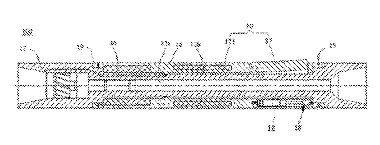
[0025]FIG. 1 shows a static push-the-bit rotary guiding device 100 (hereinafter referred to as rotary guiding device 100) provided by the present invention. The rotary guiding device 100 is able to actuate a drill bit or a drill column to make a directional deviation smoothly, thereby generating a guiding function.

[0026]According to the preferred embodiment of the present invention, an upstream is defined as a direction near a well mouth, and a downstream is defined as a direction away from the well mouth. The rotary guiding device 100 comprises a mandrel 12 having a central passage 12a. An upstream end of the mandrel 12 (an end near a left side, as shown in FIG. 1), through a thread structure thereof, is able to connect with a drilling tool or a mud motor. A downstream end of the mandrel 12 (an end near a right side, as shown in FIG. 1), through a thread structure thereof, is able to connect ...


PUM


Abstract

A static push-the-bit rotary guiding device includes: a mandrel having a central passage, wherein a circumferential groove is provided on an outer wall of the mandrel; a sleeve, which is sleeved in the circumferential groove and able to rotate independently; and a clutch, for cutting off or transferring a power from the mandrel to the sleeve. When it is unnecessary for the static push-the-bit rotary guiding device to provide a deviating force in a steady inclined section, a vertical section and a horizontal section, a rotational inertia and an interior energy storage of the rotary guiding device are not decreased, which is beneficial to highly-efficient and stable drilling of a downstream drill bit.

Description

CROSS REFERENCE OF RELATED APPLICATION[0001]This is a U.S. National Stage under 35 U.S.C 371 of the International Application PCT / CN2015 / 089713, filed Sep. 16, 2015, which claims priority under 35 U.S.C. 119(a-d) to CN 201410514459.3, filed Sep. 29, 2014.BACKGROUND OF THE PRESENT INVENTIONField of Invention[0002]The present invention relates to a technical field of petroleum drilling, and more particularly to a static push-the-bit rotary guiding device.Description of Related Arts[0003]In the field of drilling technology, the rotary steerable drilling system is widely applied. According to the requirement of trajectory control, during a rotary drilling process, the rotary steerable drilling system is able to adjust a well deviation and a direction in real-time, and has the advantages of high wellbore trajectory control precision, smooth drilled wellbore, low friction, low torque, large drilling ultimate displacement, little drilling accident, fast drilling speed, and low drilling cos...

Claims


Application Information

Patent Timeline
IPC IPC(8): E21B7/06E21B17/00E21B17/20
CPCE21B7/06E21B17/006E21B17/20E21B7/067
Inventor YANG, JINZHOUXIAO, HONGBINGWU, ZHONGHUAZHU, JIERANHAN, LAJULI, ZUOHUIZHOU, YANJUNTANG, ZHIJUN
Owner SINOPEC SHENGLI PETROLEUM ENG CO LTD DRILLING TECH RES INST
Why Eureka
Try Eureka