Osteosynthesis device

Active Publication Date: 2018-08-02
SILONY MEDICAL INT
View PDF0 Cites 1 Cited by
  • Summary
  • Abstract
  • Description
  • Claims
  • Application Information

AI Technical Summary

Benefits of technology

The invention provides an osteosynthesis device that allows for easy and cost-effective implementation of large shank diameters of bone anchors while ensuring correction of the angular position of the anchor.

Problems solved by technology

However, a drawback of osteosynthesis devices of this type is that the shank diameters of the bone anchors or bone screws that comprise an external thread for screwing into a bone or vertebral body are limited.
It is thus not possible to insert a bone anchor or bone screw that has a shank diameter that is greater than the diameter of the head into the receiving opening from the proximal end of the fork head.
Therefore, for applications that require a large shank diameter, osteosynthesis devices of this type cannot be used.
However, a drawback of an osteosynthesis device of this type is that it is not possible, or is only possible with difficulty, for a surgeon to correct the angular adjustment once the set screw has been tightened for the first time, since the clamping ring is already clamped on the conical outer surface of the clamping part.
This proves to be problematic in particular in bone screws that have already been screwed into bones or vertebral bodies.
Furthermore, the multiple-part design of the fork head is complicated to fit and expensive to manufacture.

Method used


Image

  • Osteosynthesis device
  • Osteosynthesis device
  • Osteosynthesis device

Examples


Embodiment Construction

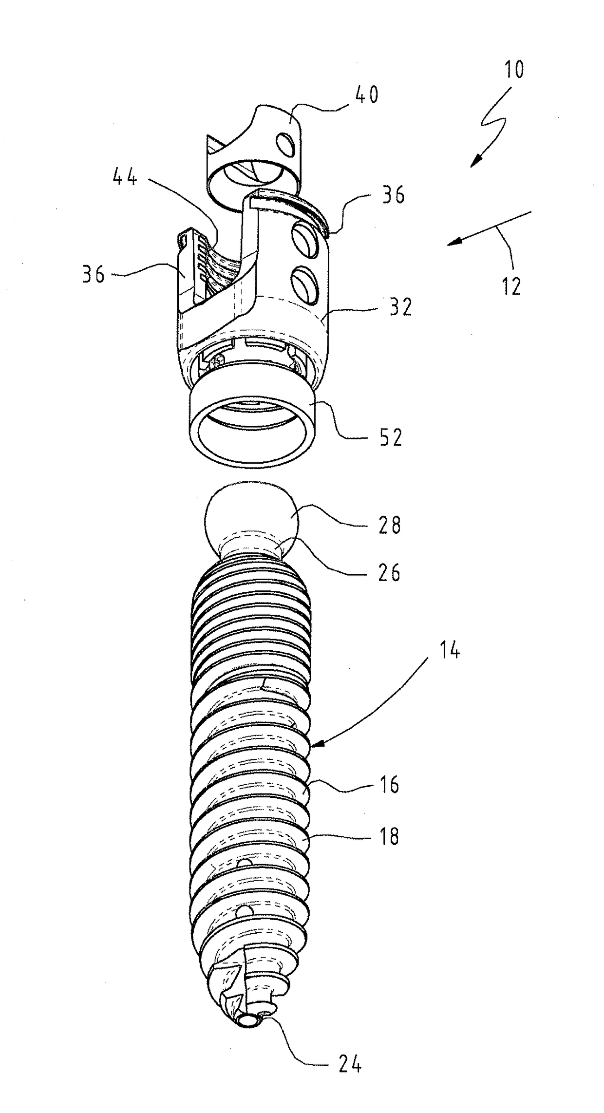
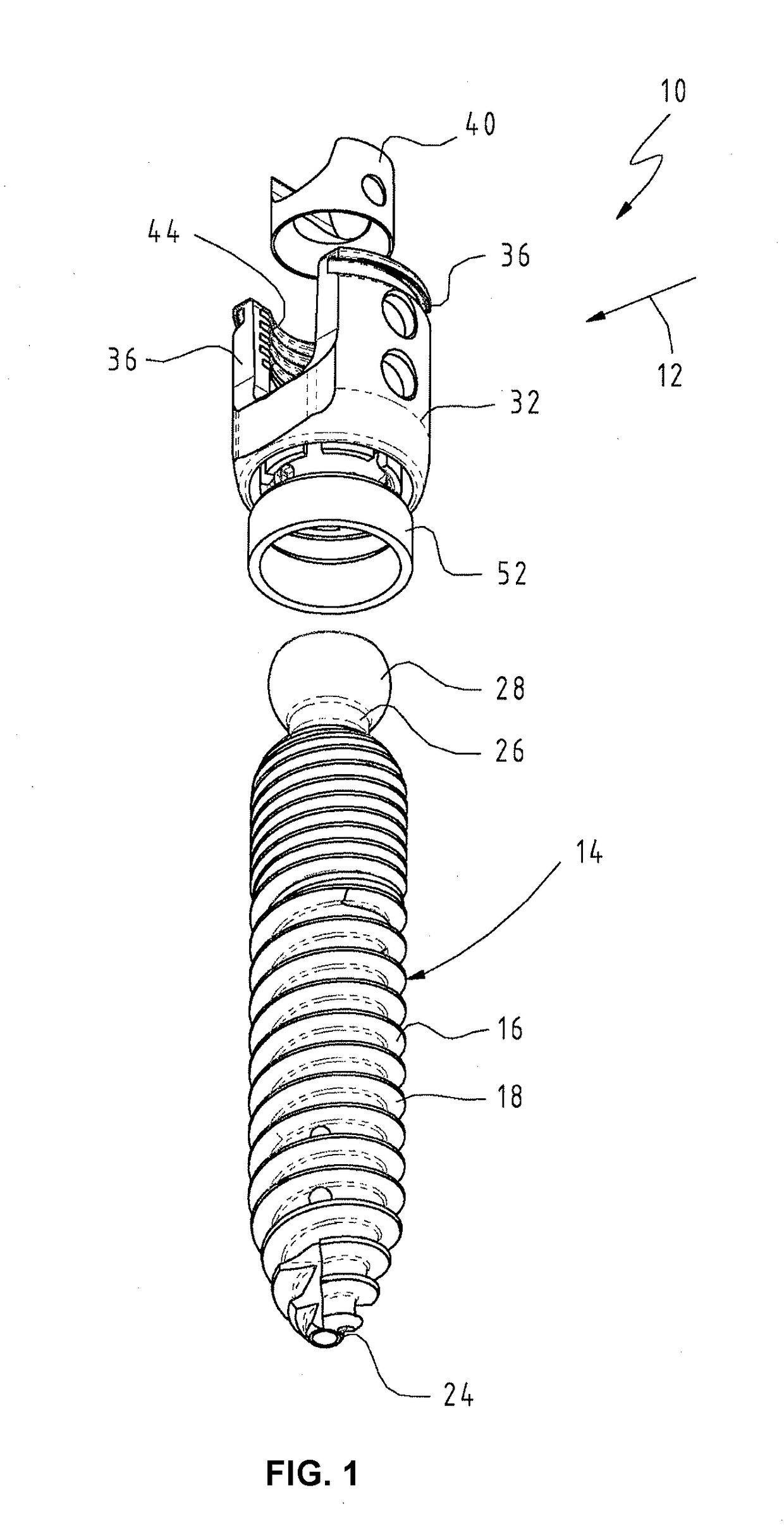
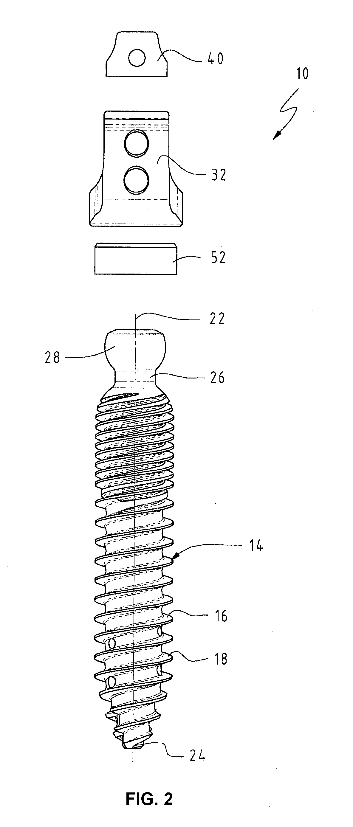
[0031]FIGS. 1 to 4 show an osteosynthesis device 10 according to the invention that is denoted as a whole by reference sign 10 and is designed as a pedicle screw, in particular as a polyaxial screw. Corresponding components and elements in the drawings are denoted by corresponding reference signs herein. FIG. 1 is an oblique view from below of the osteosynthesis device 10. FIG. 2 is an exploded side view of the osteosynthesis device 10 when viewed in the direction of the arrow 12 in FIG. 1. FIG. 3 is a non-exploded side view of the osteosynthesis device 10 according to FIG. 2 and FIG. 4 shows a section through the osteosynthesis device 10 along the line A-A according to FIG. 3.

[0032]The osteosynthesis device 10 comprises a bone anchor 14, designed as a bone screw, which comprises a shank 16 having an external thread 18. The bone anchor 14 or the shank 16 thereof is cannulated, i.e. it has a continuous longitudinal hole 20 that is concentric with a central longitudinal axis 22 of the...


PUM


Abstract

Osteosynthesis device, in particular a pedicle screw, having a bone anchor, in particular a bone screw, with a shank and a head, and having a fork head which is U-shaped in a side view and which has two arms at a proximal end area and is formed in one piece, wherein the head of the bone anchor is mounted pivotably on a distal end area of the fork head directed away from the arms, wherein the fork head has, at the distal end area, a receiving opening for the head of the bone anchor, which receiving opening is delimited in the radial direction by spring portions, wherein the spring portions are delimited radially inwards by the receiving opening and radially outwards by an annular groove arranged concentrically with respect to the receiving opening, said annular groove forming a seat for a securing element, wherein the head of the bone anchor is inserted into the receiving opening from the direction of the distal end of the fork head.

Description

BACKGROUND OF THE INVENTION[0001]The invention relates to an osteosynthesis device, in particular a pedicle screw, having the features of the preamble of claim 1.[0002]Osteosynthesis devices of this type are well known from the prior art. Osteosynthesis devices relate in particular to the field of spinal surgery, in order to align adjacent vertebral bodies and fix said bodies in a desired position relative to one another. In the process, a bone anchor is inserted into each adjacent vertebral body, specifically is typically screwed into said body in the form of a bone screw, and these adjacent bone anchors are then connected by a correction element, typically by a correction rod, which is clamped in the fork head of a relevant osteosynthesis device in a particular position desired by a surgeon. In this way, adjacent vertebral bodies are aligned and fixed relative to one another in a desired position.[0003]An osteosynthesis device of this type is known from EP 2 301 458 A1, for exampl...

Claims


Application Information

Patent Timeline
IPC IPC(8): A61B17/70
CPCA61B17/7032A61B17/7037A61B17/7098A61B17/7038A61B17/864
Inventor HEUER, FRANK
Owner SILONY MEDICAL INT
Why Eureka
Try Eureka