Gas suspension member and method

a technology of suspension member and gas suspension, which is applied in the direction of shock absorbers, manufacturing tools, transportation and packaging, etc., can solve the problems of reducing the performance and/or efficiency of the suspension system, reducing the integrity of the fluid-tight seal formed around the fitting, and the material surrounding the fitting to become separated from the connector fitting, etc., to achieve the effect of reducing the transmission of separation-causing stresses and reducing the deflection of the first end wall

Inactive Publication Date: 2010-05-06
FIRESTONE IND PROD COMPANY
View PDF40 Cites 0 Cited by
  • Summary
  • Abstract
  • Description
  • Claims
  • Application Information

AI Technical Summary

Benefits of technology

[0012]A gas suspension member in accordance with the subject matter of the present disclosure is provided that includes a first end wall with an opening formed therethrough. A second end wall is spaced from the first end wall such that a longitudinally-extending axis extends therebetween. A side wall extends between the first and second end walls and at least partially defines a gas chamber therebetween. A third end wall is attached to the first end wall across the opening thereof. A connector fitting is at least partially embedded within the third end wall such that a substantially fluid-tight seal is formed along an interface between the connector fitting and the third end wall. The connec

Problems solved by technology

Repeated flexing of the end wall, however, can, in some cases, cause the flexible material surrounding the fitting to become separated from the connector fitting.
This typically compromises the seal around the connector fitting, resulting in pressurized gas loss, which can reduce performance and/or efficiency of the suspension system among other problems.
One significant source of separation is caused by inflation-induced stresses along the flexible wall on which the fitting is installed.
This can undesirably result the loss of integrity of the fluid-tight seal formed around the

Method used


Image

  • Gas suspension member and method
  • Gas suspension member and method
  • Gas suspension member and method

Examples


Embodiment Construction

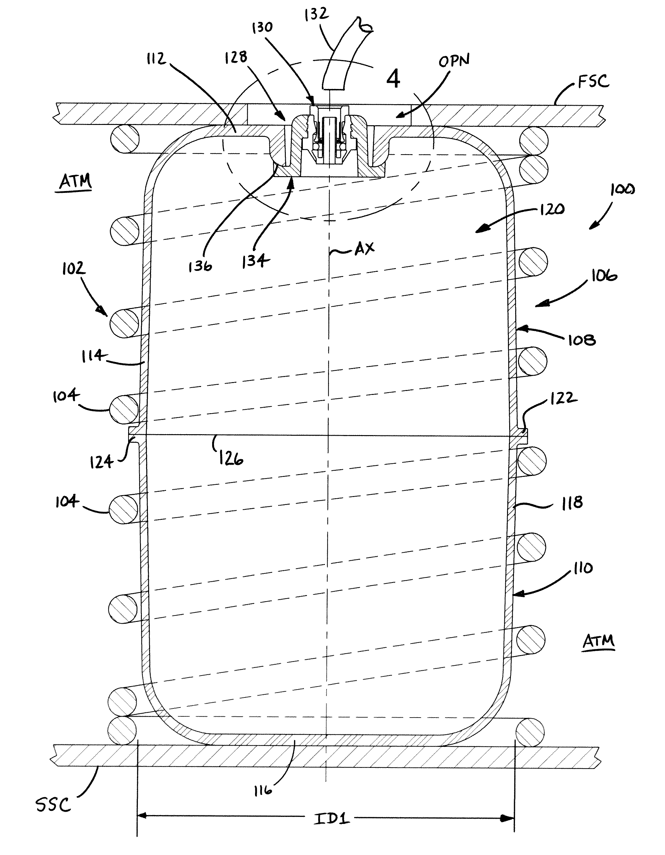
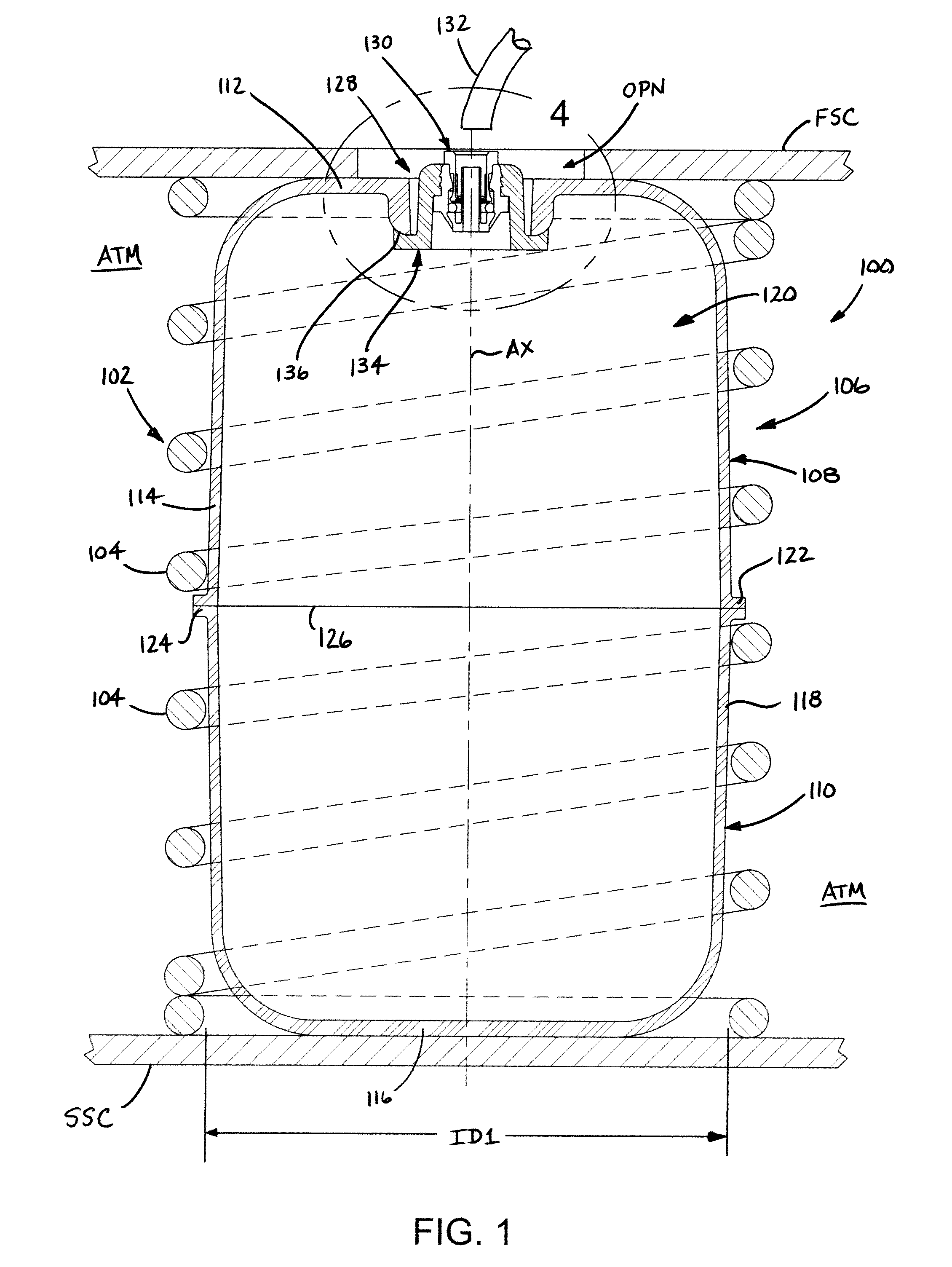
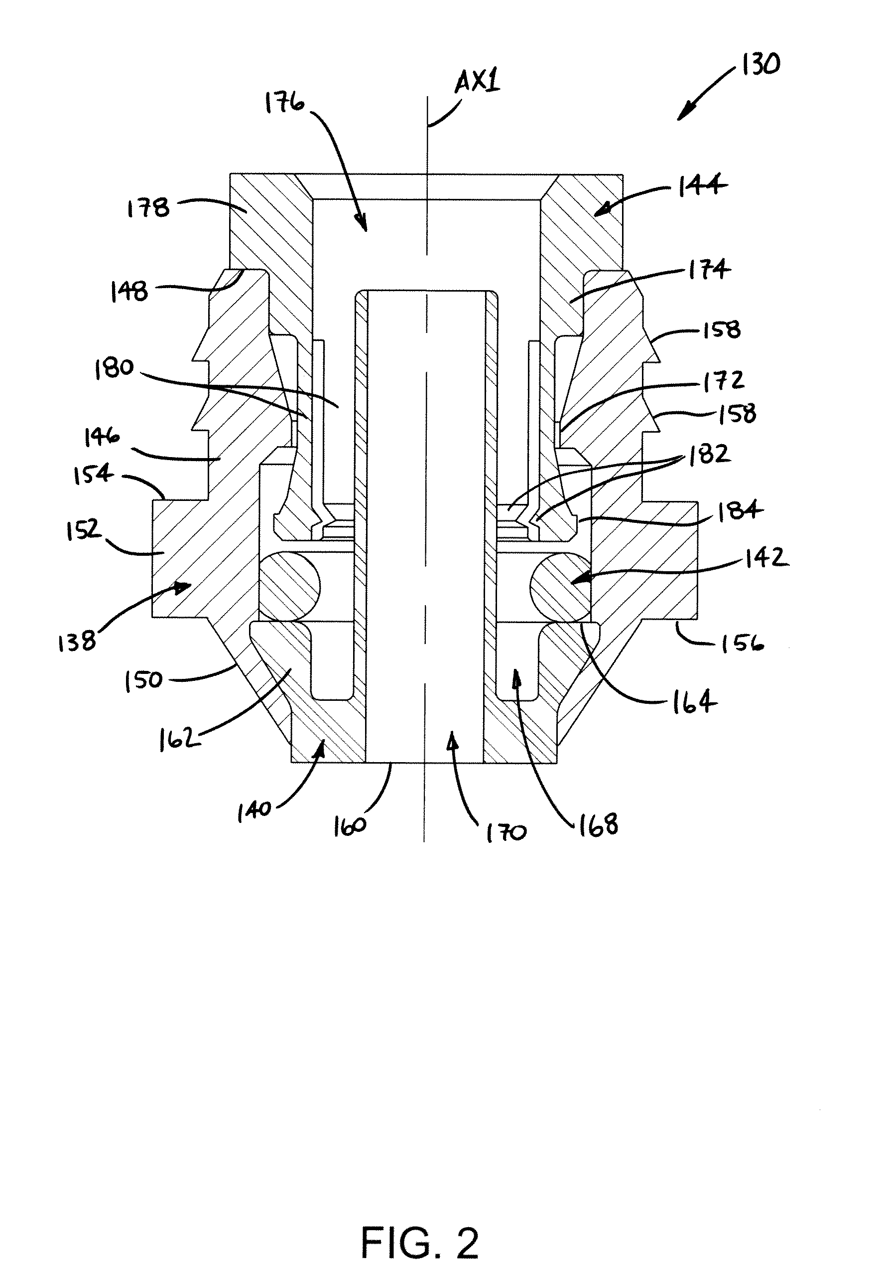
[0021]Turning now to drawings wherein the showings are for the purpose of illustrating preferred embodiments of the subject matter of the present disclosure only and which showings are not to be construed as being in any way limiting, FIG. 1 illustrates a gas suspension assembly 100 that includes first and second suspension elements or devices supported between opposing structural members, such as first and second structural components FSC and SSC of an associated vehicle (not shown), for example. In the exemplary arrangement shown in FIG. 1, gas suspension assembly 100 includes a conventional compression spring 102 that is formed from a spring element (e.g., a length of metal wire or rod) having a plurality of coils 104 that extend circumferentially about a longitudinally-extending axis AX. An interior area (not numbered) is provided within the plurality of coils, such as may be defined within inside dimension ID1, for example.

[0022]Gas suspension assembly 100 also includes a gas s...


PUM

PropertyMeasurementUnit
Thicknessaaaaaaaaaa
Stiffnessaaaaaaaaaa
Polymericaaaaaaaaaa

Abstract

A gas suspension member includes a first section and a second section. The first section includes an end wall and a side wall that at least partially form an inner chamber. An opening is formed through the end wall. A connector fitting is embedded within a cover wall that extends across the opening. The end wall has a first flexural stiffness and the cover wall has a second flexural stiffness that is greater than the first flexural stiffness of the end wall. A gas suspension assembly includes a first spring device used in combination with the gas suspension member. A method of forming a gas suspension member is also disclosed.

Description

BACKGROUND[0001]The subject matter of the present disclosure broadly relates to the art of suspension systems and, more particularly, to a gas suspension member adapted to interconnect with a gas transmission line as well as a method of forming such a gas suspension member.[0002]The subject matter of the present disclosure finds particular application in association with gas suspension members used on suspension systems of vehicles, and will be discussed herein with particular reference thereto. However, it will be appreciated that the subject gas suspension member and method are equally applicable for use in other applications and environments, and are not intended to be in any way limited to use in the applications discussed herein, which are merely exemplary.[0003]Gas suspension members having an inlet for connecting a gas transmission line are generally well known. One example of such a gas suspension member is disclosed in U.S. Pat. No. 6,145,894 to Myers, which is hereby incor...

Claims


Application Information

Patent Timeline
IPC IPC(8): F16F9/02B23P19/04
CPCB60G11/27B60G11/58B60G2204/126B60G2206/424F16F9/04F16F9/43Y10T29/49879
Inventor LEONARD, JOSHUA R.
Owner FIRESTONE IND PROD COMPANY
Why Eureka
Try Eureka