Rendering system

Active Publication Date: 2018-07-19
FRAUNHOFER GESELLSCHAFT ZUR FOERDERUNG DER ANGEWANDTEN FORSCHUNG EV
View PDF9 Cites 1 Cited by
  • Summary
  • Abstract
  • Description
  • Claims
  • Application Information

AI Technical Summary

Benefits of technology

This patent is about a method for identifying a loudspeaker-enclosure-microphone system using a rendering filters transfer function matrix. The method reduces computational complexity by using a rendering filters transfer function matrix instead of directly estimating the loudspeaker-enclosure-microphone transfer function matrix. This approach allows for the estimation of an audio system's transfer function matrix using the information provided by an object-based rendering system. The method is flexible and can either minimize peak computational complex or average computational complexity. This invention can be beneficial for computationally powerful devices or devices with limited resources, such as multicore smartphones or tablets. It also reduces the peak load produced by the signal processing application, which is useful for identifying very large systems or for sharing one processing device with other time-critical applications. Overall, this invention reduces computational complexity and improves the efficiency of identifying loudspeaker-enclosure-microphone systems.

Problems solved by technology

In practice, multichannel acoustic system identification suffers from the strongly cross-correlated loudspeaker signals typically occurring when rendering virtual acoustic scenes with more than one loudspeaker: the computational complexity grows with at least the number of acoustical paths through the MIMO system, which is NL·NM for NL loudspeakers and NM microphones.
None of these approaches employs side information from an object-based rendering system.

Method used


Image

  • Rendering system
  • Rendering system
  • Rendering system

Examples


Embodiment Construction

[0043]Equal or equivalent elements or elements with equal or equivalent functionality are denoted in the following description by equal or equivalent reference numerals.

[0044]In the following description, a plurality of details are set forth to provide a more thorough explanation of embodiments of the present invention. However, it will be apparent to one skilled in the art that embodiments of the present invention may be practiced without these specific details. In other instances, well-known structures and devices are shown in block diagram form rather than in detail in order to avoid obscuring embodiments of the present invention. In addition, features of the different embodiments described hereinafter may be combined with each other unless specifically noted otherwise.

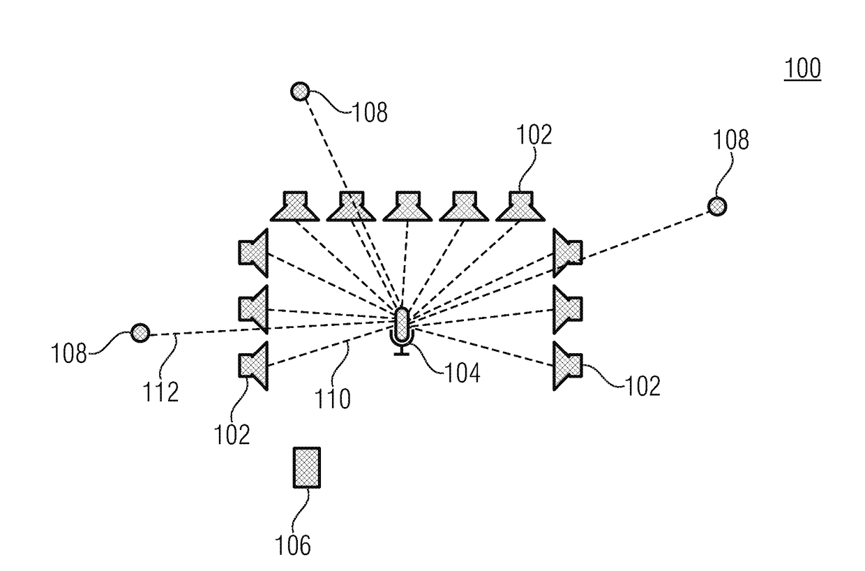
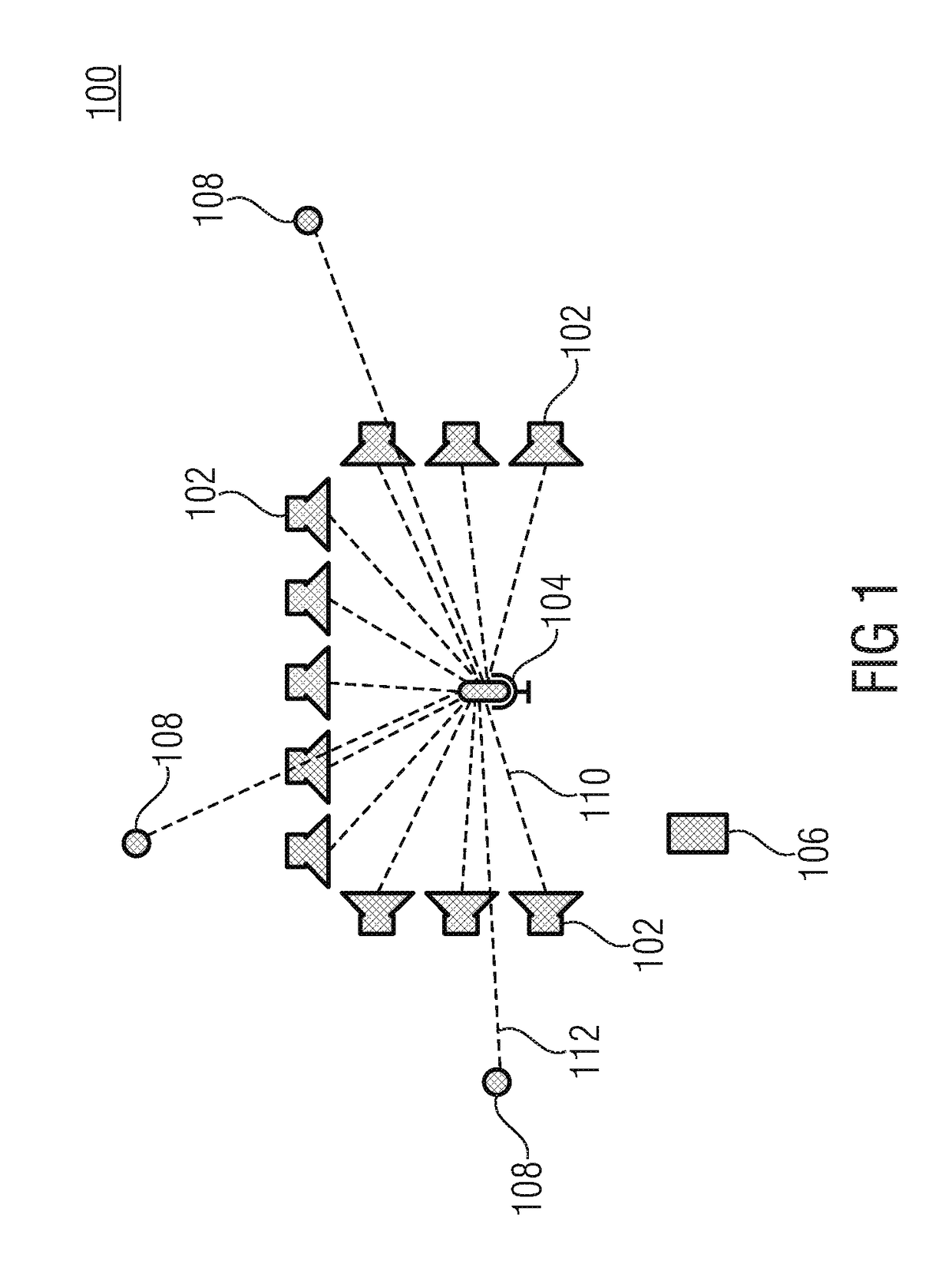
[0045]FIG. 1 shows a schematic block diagram of a rendering system 100 according to an embodiment of the present invention. The rendering system 100 comprises a plurality of loudspeakers 102, at least one microphon...


PUM


Abstract

A rendering system including a plurality of loudspeakers, at least one microphone and a signal processing unit. The signal processing unit is configured to determine at least some components of a loudspeaker-enclosure-microphone transfer function matrix estimate describing acoustic paths between the plurality of loudspeakers and the at least one microphone using a rendering filters transfer function matrix using which a number of virtual sources is reproduced with the plurality of loudspeakers.

Description

CROSS-REFERENCE TO RELATED APPLICATIONS[0001]This application is a continuation of co-pending International Application No. PCT / EP2016 / 069074, filed Aug. 10, 2016, which is incorporated herein by reference in its entirety, and additionally claims priority from German Application No. DE 102015218527.3, filed Sep. 25, 2015, which is incorporated herein by reference in its entirety.[0002]Embodiments relate to a rendering system and a method for operating the same. Some embodiments relate to a source-specific system identification.BACKGROUND OF THE INVENTION[0003]Applications, such as Acoustic Echo Cancellation (AEC) or Listening Room Equalization (LRE) involve the identification of acoustic Multiple-Input / Multiple-Output (MIMO) systems. In practice, multichannel acoustic system identification suffers from the strongly cross-correlated loudspeaker signals typically occurring when rendering virtual acoustic scenes with more than one loudspeaker: the computational complexity grows with at...

Claims


Application Information

Patent Timeline
IPC IPC(8): H04S7/00H04R5/02
CPCH04S7/301H04R5/02H04S2400/11H04S2420/01H04S2400/15H04S2400/09H04S2420/11H04S2420/13
Inventor HOFMANN, CHRISTIANKELLERMANN, WALTER
Owner FRAUNHOFER GESELLSCHAFT ZUR FOERDERUNG DER ANGEWANDTEN FORSCHUNG EV
Why Eureka
Try Eureka