Vehicle control apparatus
a technology for controlling apparatus and vehicles, which is applied in mechanical apparatus, external condition input parameters, transportation and packaging, etc., can solve the problems of not being able to control the vehicle, and the vehicle cannot be controlled based, so as to increase the friction force and maintain high friction force. , the effect of increasing the friction for
- Summary
- Abstract
- Description
- Claims
- Application Information
AI Technical Summary
Benefits of technology
Problems solved by technology
Method used
Image
Examples
first embodiment
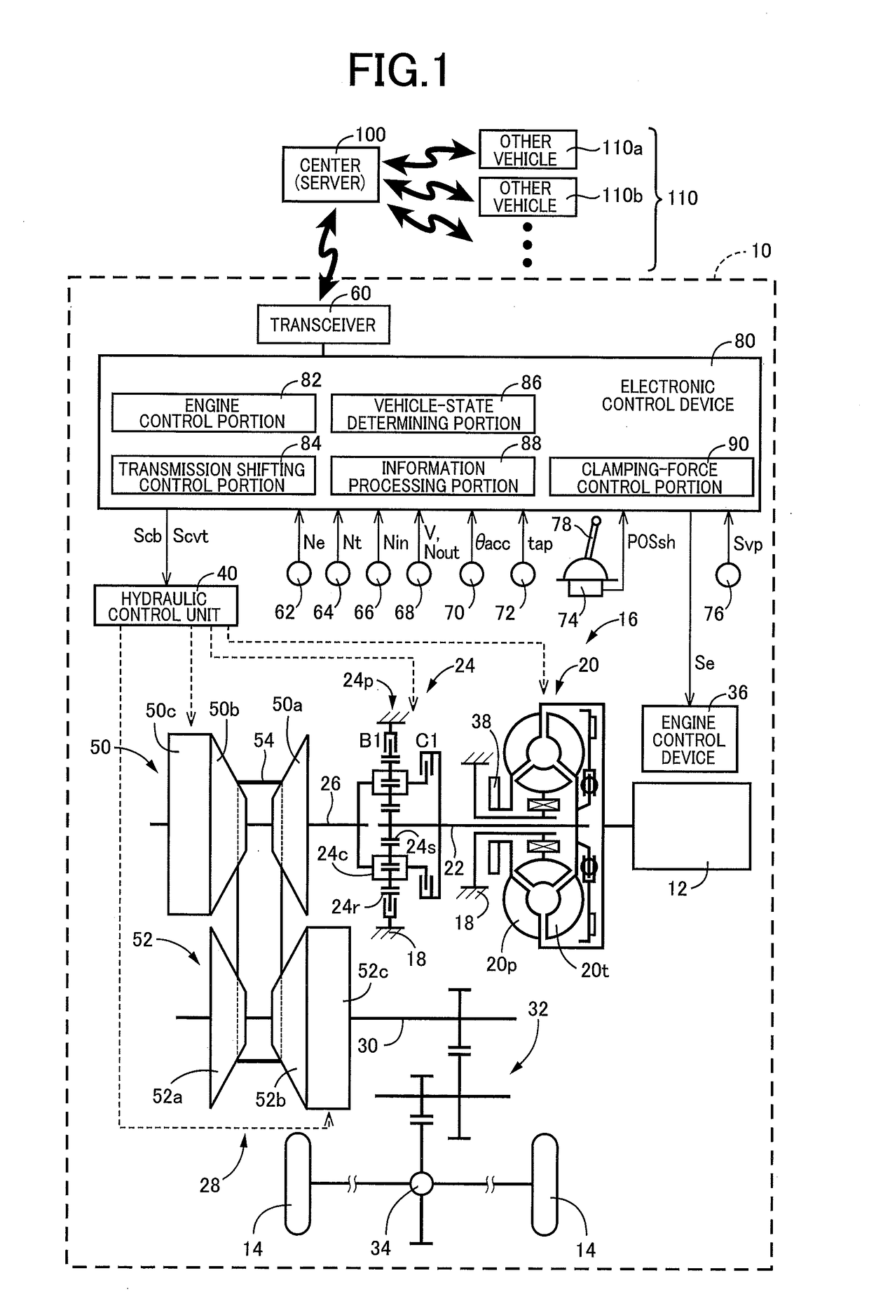
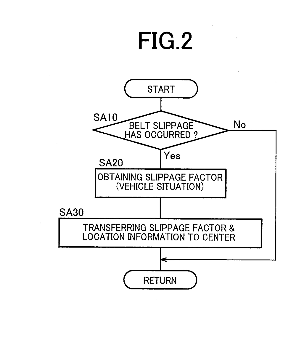
[0035]Reference is first made to FIG. 1, which is a schematic view showing a construction of a vehicle 10 to be controlled by a control apparatus according to the present invention, and major control functions and control portions of the control apparatus. As shown in FIG. 1, the vehicle 10 is provided with an engine 12 functioning as a drive power source, drive wheels 14 and a power transmission device 16 provided in a power transmitting path between the engine 12 and the drive wheels 14. The power transmission device 16 includes a non-rotary member in the form of a casing 18, a fluid-operated type power transmitting device in the form of a known torque converter 20 that is connected to the engine 12, a turbine shaft 22 connected to the torque converter 20, a forward / reverse switching device 24 connected to the turbine shaft 22, an input shaft 26 connected to the forward / reverse switching device 24, a belt-type continuously variable transmission 28 connected to the input shaft 26, ...
second embodiment
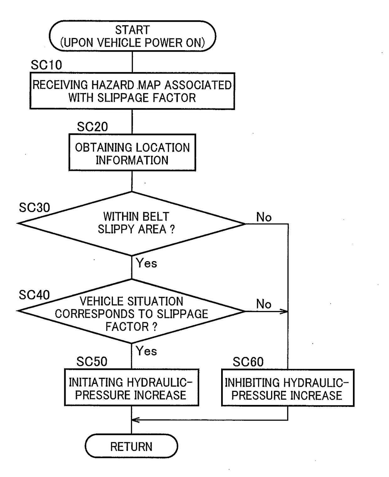
[0072]In the above-described first embodiment, when the vehicle 10 is located in the at least one belt slippy area represented in the hazard map MAPbelt of the belt slippage, the hydraulic-pressure increasing control is executed. However, the belt slippage could be caused even when the hydraulic-pressure increasing control is executed. In this case, it is preferable to further increase the pulley hydraulic pressure. Further, since an increase of the pulley hydraulic pressure could reduce durability of the belt and / or reduce fuel economy, it is preferable to reduce the pulley hydraulic pressure as long as the increase of the pulley hydraulic pressure is not required. In the present second embodiment, the certain pressure value Pf, by which the pulley hydraulic pressure is increased upon execution of the hydraulic-pressure increasing control, is changed, is changed depending on frequency of occurrence of the belt slippage. When the hydraulic-pressure increasing control is not executed...
third embodiment
[0080]In the above-described first and second embodiments, the belt clamping force is controlled to be increased, with reference to the hazard map MAPbelt that is received from the center 100. However, there could be a case where the vehicle 10 cannot receive the hazard map MAPbelt from the center 100, for some reason. In this case, the belt clamping force could not be controlled to be increased. In the present third embodiment, when being unable to receive the hazard map MAPbelt from the center 100, the vehicle 10 receives, from one of the other vehicles 110, a hazard map MAPbelt that is substantially the same as the hazard map MAPbelt owned by the center 100. In this sense, each of the other vehicles 110 as well as the center 100 is considered to correspond to the external device that is located outside the vehicle 10. Further, the transceiver 60 is considered to be a device configured to communicate the other vehicles 110 as well as to the center 100. Thus, the electronic control...
PUM
 Abstract
Description
Claims
Application Information
 - R&D
- Intellectual Property
- Life Sciences
- Materials
- Tech Scout
- Unparalleled Data Quality
- Higher Quality Content
- 60% Fewer Hallucinations
Browse by: Latest US Patents, China's latest patents, Technical Efficacy Thesaurus, Application Domain, Technology Topic, Popular Technical Reports.
© 2025 PatSnap. All rights reserved.Legal|Privacy policy|Modern Slavery Act Transparency Statement|Sitemap|About US| Contact US: help@patsnap.com


