Method for the defined separation of a glass layer on an inner wall of a preform and preform and communication system

a technology of communication system and glass layer, which is applied in the field of defined separation of glass layer on an inner wall of a preform and preform and communication system, can solve the problems of undefined and/or strongly varying thicknesses and profiles, and considerable flaws in the refractive index profile, and achieve the effect of constant blank mold diameter and higher fiber yield

Active Publication Date: 2018-07-19
J FIBER GMBH
View PDF5 Cites 0 Cited by
  • Summary
  • Abstract
  • Description
  • Claims
  • Application Information

AI Technical Summary

Benefits of technology

[0008]Most of the mentioned methods are adapted to maintain a constant diameter of the blank mold during the coating process. However, the outer diameter has almost no influence on the deposition that occurs inside the tube. These methods therefore lead to undefined and / or strongly varying thicknesses and profiles of individual glass layers deposited on the inside. This results partly in considerable flaws in the refractive index profile. Multi-mode fibers manufactured in accordance with the prior art are therefore meteorologically characterized and correspondingly assigned to quality classes. In so doing, flaws in the refractive index profile have a considerable influence on the proportion of fibers of the individual quality classes. Fewer flaws in the refractive index profile and smaller refractive index deviations provides a higher yield of fibers in the desired quality classes.
[0009]An aspect of the present invention is to improve upon the prior art.
[0010]In an embodiment, the present invention provides a method for a defined deposition of a glass layer on an inner wall of a preform for an optical fiber and / or for setting a refractive index profile of the preform for a multi-mode fiber. The method includes providing the preform comprising a cavity and an inner wall which defines an inner diameter of the preform, and spreading a deposition gas at a flow speed (v) in the cavity of the preform so as to provide the defined deposition of the glass layer. The defined deposition is performed at a reduced change in the flow speed a*Δv, where a<1. Based on the defined deposition, a change in the flow speed (Δv):

Problems solved by technology

These methods therefore lead to undefined and / or strongly varying thicknesses and profiles of individual glass layers deposited on the inside.
This results partly in considerable flaws in the refractive index profile.
In so doing, flaws in the refractive index profile have a considerable influence on the proportion of fibers of the individual quality classes.

Method used


Image

  • Method for the defined separation of a glass layer on an inner wall of a preform and preform and communication system
  • Method for the defined separation of a glass layer on an inner wall of a preform and preform and communication system
  • Method for the defined separation of a glass layer on an inner wall of a preform and preform and communication system

Examples


Embodiment Construction

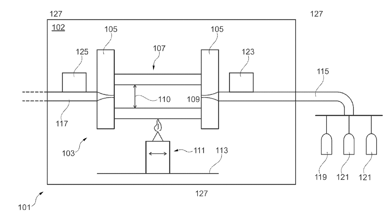
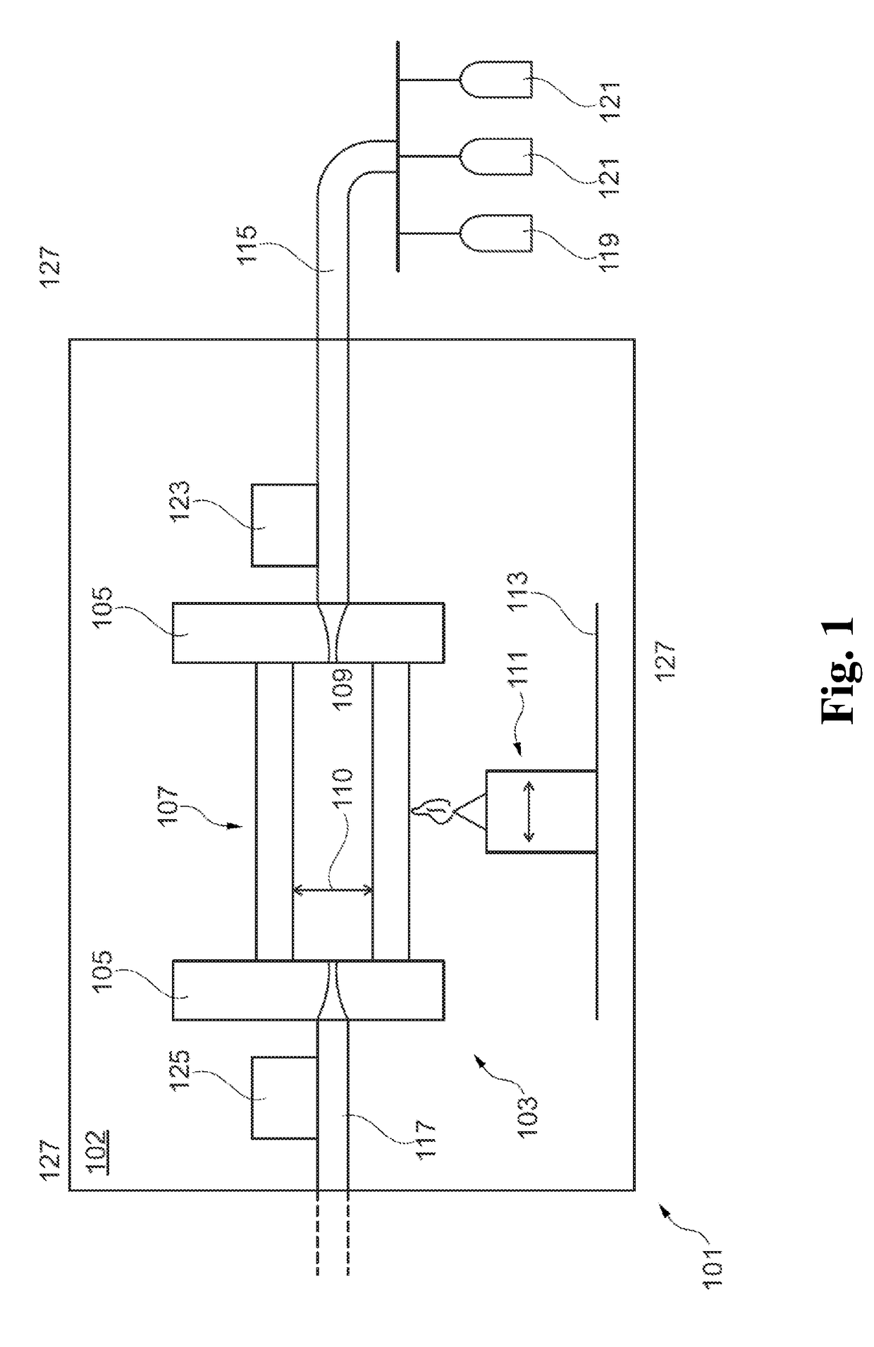
[0013]In an embodiment, the present invention provides a method for a defined deposition of a glass layer on an inner wall of a blank mold for an optical fiber and / or for setting a refractive index profile of a blank mold for a multi-mode fiber, wherein a deposition gas spreads at a flow speed (v) in a cavity of the blank mold formed by the inner wall, wherein a change in the speed of the flow:

Δv=4Qπ·(1di2-1di+12)

forms at a volume flow (Q), the first diameter (di) and the second diameter (di+1), wherein the deposition is carried out at a reduced change in flow speed a*Δv, wherein a<1.

[0014]The proposed method allows for a minimizing of disruptive effects during creation of a refractive index profile and for the refractive index profile to be set in a targeted manner while open-loop-controlling the refractive index, in particular by specifying the volume flows. This consequently provides a yield of fibers with a specified bandwidth and thus a higher yield of desired quality metrics.

[...


PUM

PropertyMeasurementUnit
core diameteraaaaaaaaaa
inner diameteraaaaaaaaaa
outer diameteraaaaaaaaaa

Abstract

A method for a defined deposition of a glass layer on an inner wall of a preform for an optical fiber and/or for setting a refractive index profile of the preform for a multi-mode fiber. The method includes providing the preform having a cavity and an inner wall which defines an inner diameter of the preform, and spreading a deposition gas at a flow speed (v) in the cavity of the preform so as to provide the defined deposition of the glass layer. The defined deposition is performed at a reduced change in the flow speed a*Δv, where a<1. Based on the defined deposition, a change in the flow speed (Δv):
Δv=4Qπ·(1di2-1di+12)
forms at a volume flow (Q), a first diameter (di), and a second diameter (di+1).

Description

CROSS REFERENCE TO PRIOR APPLICATIONS[0001]This application is a U.S. National Phase application under 35 U.S.C. § 371 of International Application No. PCT / DE2016 / 100311, filed on Jul. 13, 2016 and which claims benefit to German Patent Application No. 10 2015 112 382.7, filed on Jul. 29, 2015. The International Application was published in German on Feb. 2, 2017 as WO 2017 / 016539 A1 under PCT Article 21(2).FIELD[0002]The present invention relates to a method for the defined deposition of a glass layer on an inner wall of a preform / blank mold for an optical fiber and / or for setting a refractive index profile of a preform / blank mold for a multi-mode fiber, wherein a deposition gas is guided at a flow speed (v) in a cavity of the preform / blank mold formed by the inner wall. The present invention also relates to a glass fiber and to a communication system.BACKGROUND[0003]U.S. Pat. No. 4,813,989 describes a method for a closed-loop control of a diameter. A defined amount of gas is here b...

Claims


Application Information

Patent Timeline
Patent Type & Authority Applications(United States)
IPC IPC(8): C03B37/018C03B37/025
CPCC03B37/01807C03B37/01861C03B37/0253C03B2203/26C03B2207/70
Inventor HANF, ROBERTGENZ, CHRISTIANBREHM, LOTHAR
Owner J FIBER GMBH
Why Eureka
Try Eureka