
Method and apparatus for model-based leak detection of a pipe network

Active Publication Date: 2018-07-12
SENSUS SPECTRUM LLC
View PDF6 Cites 9 Cited by
  • Summary
  • Abstract
  • Description
  • Claims
  • Application Information

AI Technical Summary

Benefits of technology

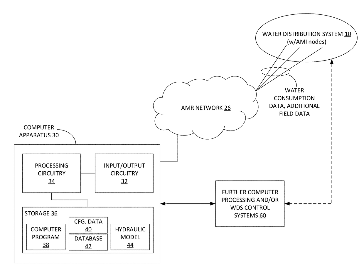
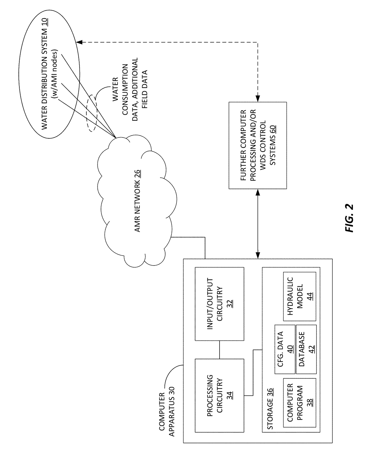
The present patent relates to a method and apparatus for detecting leaks in a water distribution system using a hydraulic model and consumption data from water meters. The technical effect of the patent is to improve the accuracy and resolution of the hydraulic model by obtaining more accurate, higher-resolution water demand values for service nodes and using real-time or near-real-time data from the water meters. This allows for more accurate control, forecasting, and other uses of the hydraulic model. The method includes automatically associating each water meter with a respective service node, calculating water demand values for each service node, and performing a control operation for the water distribution system based on the estimated water flows and pressures.

Problems solved by technology

However, such data sets typically lack the resolution and accuracy to make accurate consumption estimates for particular times or days.
Moreover, the mechanisms for associating actual consumption in the water distribution system with the modeled service nodes are simplistic and prone to inaccuracies, e.g., based on simple proximity.
The major errors occur because often there is no historical data.
To the extent that actual consumption in the water distribution system is attributed to the wrong service node in the hydraulic model, the hydraulic model will necessarily produce inaccurate results for control, forecasting, or other uses, and model adaptations tainted by such inaccuracies may worsen, rather than improve the model accuracy.
Treating and pumping water that does not supply legitimate customers such as through leaks, theft, or faulty metering increases costs, reduces water availability, and contributes greenhouse gases.
This accounting identifies the amount of non-revenue water that is produced within the system, but does not help to actually locate leaks, theft, or faulty consumption meters.
Drawbacks of these step tests include the manpower required and the required interruptions to service.
Further, the step test does not help identify the location of the leak beyond placing it between two valves.
Further complications arise when the pipe material is plastic or other factors dampen the soundwaves.

Method used


Image

  • Method and apparatus for model-based leak detection of a pipe network
  • Method and apparatus for model-based leak detection of a pipe network
  • Method and apparatus for model-based leak detection of a pipe network

Examples


Embodiment Construction

[0035]Through experimentation and analysis, the present inventors have developed a Leak Detection System that significantly improves the accuracy of leak detection while reducing the effort required by the utility relative to the current state of the art.

[0036]In one embodiment, the Leak Detection System comprises pressure sensors, advanced metering infrastructure at points of consumption, and a proprietary algorithm. The present inventors have found that pressure sensors are particularly suited for this purpose because they are relatively inexpensive and easier to install than other sensors and meters. Pressure sensors can also be installed without requiring a shutdown. In many cases they can be installed at available ports without excavation. Likewise, having an advanced metering infrastructure is also convenient since it also provides the utility with various other services. However, it should be recognized that other types of sensors may also be used in the presently disclosed L...


PUM


Abstract

A method, apparatus, and system for leak detection in a distribution network having consumption meters. The distribution network is divided into zones having an upstream location and a downstream location. An upstream pressure sensor detects the upstream pressure at the upstream location and the downstream pressure sensor detects the detected downstream pressure at the downstream location. A downstream pressure lookup table is used to determine an expected pressure at each downstream location based on a range of hypothetical upstream pressures at the corresponding upstream location and consumption data from the consumption meters. The expected pressure and the detected downstream pressure at each downstream location are compared to determine if the calculated discrepancy exceeds a discrepancy threshold. If a discrepancy exceeds a discrepancy threshold, a leak location lookup table containing a set of potential leak locations based on a range of hypothetical discrepancies is used to determine a set of probable leak locations.

Description

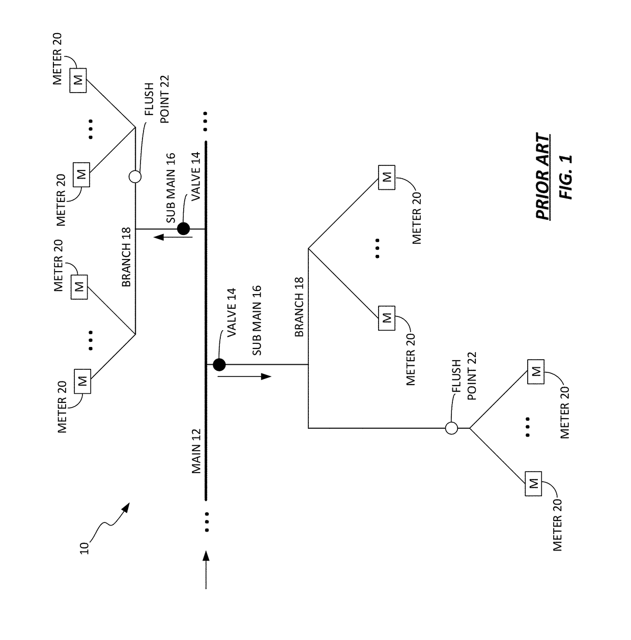
BACKGROUND[0001]The Background and Summary are provided to introduce a foundation and a selection of concepts that are further described below in the Detailed Description. The Background and Summary are not intended to identify key or essential features of the potentially claimed subject matter, nor are they intended to be used as an aid in limiting the scope of the potentially claimed subject matter.[0002]The present disclosure relates to leak detection for a pipe network or a subset of a pipe network. More specifically, the present disclosure relates to a method and apparatus for model-based leak detection using consumption meters along with sensors within the pipe network.[0003]Presently, water distribution systems deliver water to households, commercial buildings, and industrial facilities through a network that includes tanks, pipes, and pumps. FIG. 1 depicts a representative water distribution system 10. The water distribution system 10 includes a water main 12 and valves 14 t...

Claims


Application Information

Patent Timeline
IPC IPC(8): G01M3/28G06F17/50
CPCG06F17/5009G01M3/2815E03B7/07E03B7/071E03B7/072E03B7/075E03B7/078G06F30/20
Inventor BARKER, ZACHARY A.SHAFIEE, MICHAEL ESHANSMITH, TRAVISRASEKH, AMINCAMPBELL, BRUCEMULLER, GRANT
Owner SENSUS SPECTRUM LLC
Learn More