Condensate neutralizer system including condensate device health monitoring

a technology of condensate neutralizer and health monitoring, which is applied in the direction of domestic stoves or ranges, heating types, separation processes, etc., can solve the problems of putting the burden of proper condensate neutralization on the shoulders of users or maintenance personnel, and stakeholders have neglected to come up with or follow maintenance schedules, so as to facilitate the replenishment of neutralizing materials and reduce the amount of neutralizing materials

Active Publication Date: 2018-07-05
INTELLIHOT
View PDF0 Cites 2 Cited by
  • Summary
  • Abstract
  • Description
  • Claims
  • Application Information

AI Technical Summary

Benefits of technology

[0031]An object of the present invention is to provide a means for facilitating the replenishment of neutralizing materials when the amount of neutralizing materials has been detected to be low.
[0032]An object of the present invention is to provide a means for monitoring the health of a condensate generating device by verifying the efficiency at which the condensate generating device operates.

Problems solved by technology

Condensate is an acidic solution containing various concentrations of nitric, nitrous, sulfuric, sulfurous acids and hydrochloric acids and can be harmful for drainage pipes, septic tanks, treatment plants and other waste handling systems.
However, conventional condensate neutralizer systems put the burden of proper condensate neutralization on the shoulders of their users or maintenance personnel, or collectively their stakeholders.
In many occasions, stakeholders have neglected to either come up with or follow maintenance schedules.
Further, preventative maintenance of condensate neutralizing materials may cause unnecessary replacement of still effective neutralizing materials, thereby causing unnecessary waste not only in the neutralizing materials but also additional labor.
Further, in Tomlinson, there are no measures to determine the quality of the effluent.
Therefore, it is possible that the condensate is not properly neutralized (even with some neutralizing material remaining in the neutralizer but still discharged.

Method used


Image

  • Condensate neutralizer system including condensate device health monitoring
  • Condensate neutralizer system including condensate device health monitoring
  • Condensate neutralizer system including condensate device health monitoring

Examples


Embodiment Construction

[0095]The term “about” is used herein to mean approximately, roughly, around, or in the region of. When the term “about” is used in conjunction with a numerical range, it modifies that range by extending the boundaries above and below the numerical values set forth. In general, the term “about” is used herein to modify a numerical value above and below the stated value by a variance of 20 percent up or down (higher or lower).

[0096]The term “stakeholder” is used herein to mean a user, maintenance personnel, repair personnel, etc., or any personnel that uses, maintains or repairs, owns or manages a condensate neutralizer system and / or a condensate generating device connected to the condensate neutralizer system.

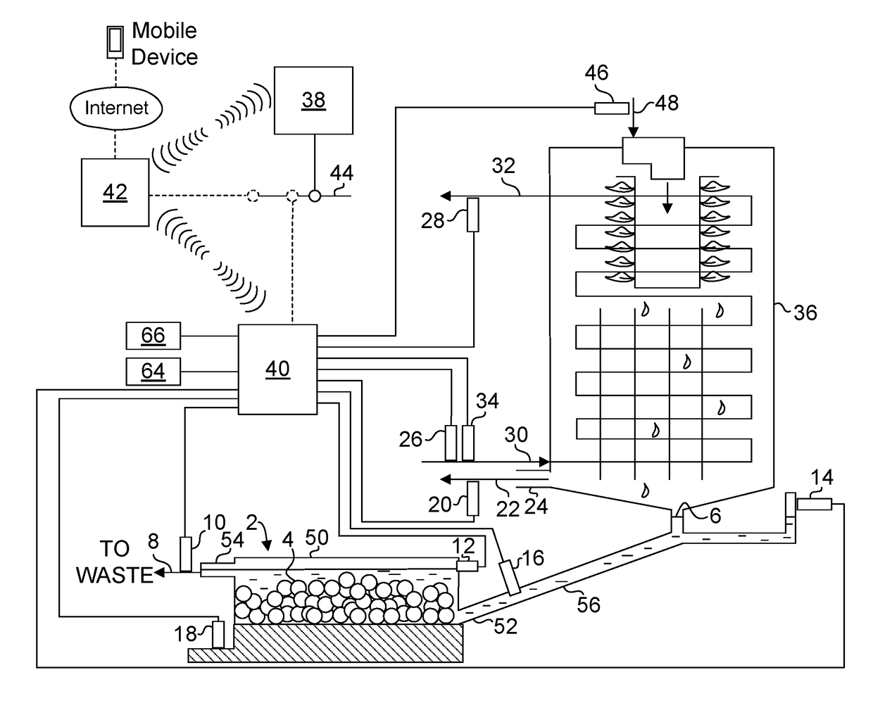
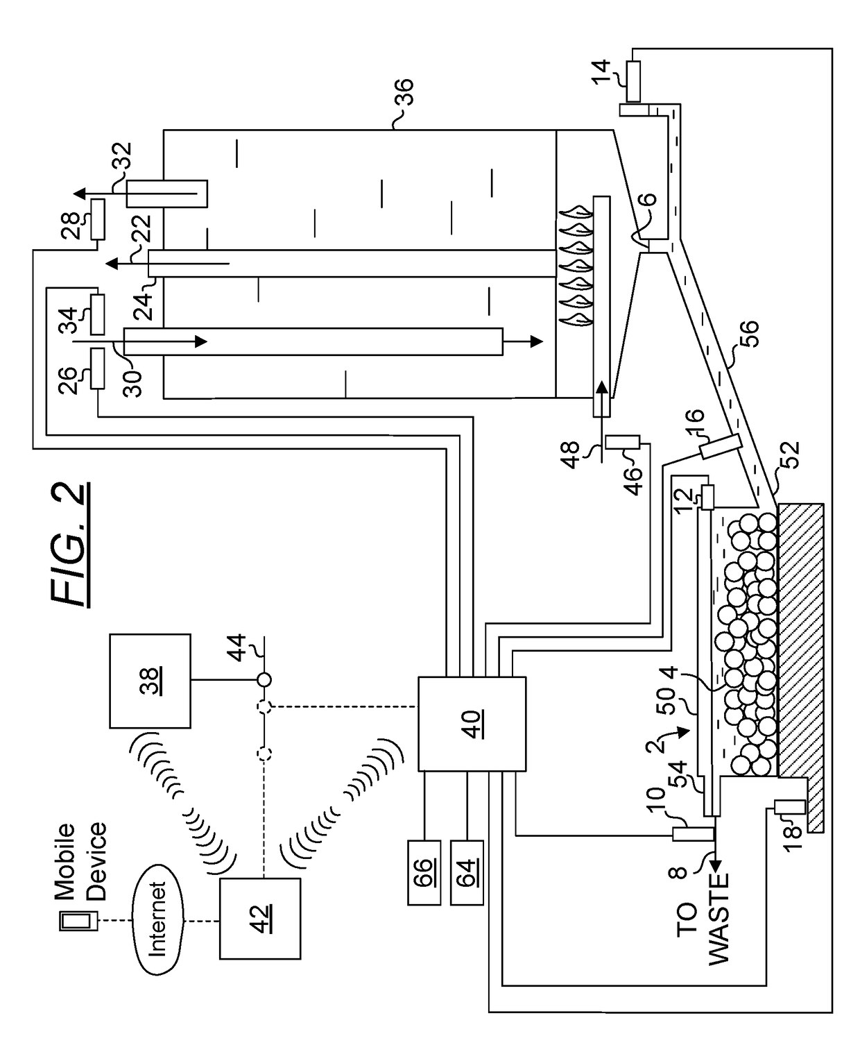
[0097]FIG. 1 is a diagram depicting a condensate neutralizer system 2 and the equipment configured for monitoring the health of a tankless water heater which supplies condensate neutralized in the condensate neutralizer system 2. The condensate neutralizer system 2 includes a c...


PUM

PropertyMeasurementUnit
pHaaaaaaaaaa
temperatureaaaaaaaaaa
sizeaaaaaaaaaa

Abstract

A condensate neutralizer system for treating condensate of a condensate generating device, the condensate neutralizer system including a container having an inlet and an outlet, the inlet is configured to receive condensate from the condensate generating device, the container is configured to contain a condensate neutralizing material useful for treating the condensate and the outlet is configured to drain condensate treated with the condensate neutralizing material; a controller; and a pH meter functionally connected to said controller, the pH meter is configured to take pH measurements of the treated condensate, the measurements are configured to be compared to a fault pattern, wherein the fault pattern is defined by a condition where the pH measurements are lower than a pre-determined pH level and if a fault is determined to exist, a warning is raised or a delivery of replenishment of the condensate neutralizing material is initiated.

Description

PRIORITY CLAIM AND RELATED APPLICATIONS[0001]This non-provisional application claims the benefit of priority from provisional application U.S. Ser. No. 62 / 439,918 filed Dec. 29, 2016. Said application is incorporated by reference in its entirety.BACKGROUND OF THE INVENTION1. The Field of the Invention[0002]The present invention relates to a condensate neutralizer system. More specifically, the present invention is directed to a condensate neutralizer system adapted to receive condensate from a condensate generating device, the condensate neutralizer system is capable of indicating the depletion of condensate neutralizing material and alerting a stakeholder of such a condition and health monitoring for the condensate generating device.2. Background Art[0003]Condensate generation is one of the hallmarks of a high efficiency (e.g., greater than 90% efficiency) condensing combustion system. A high efficiency condensing combustion system achieves high efficiency by condensing water vapor...

Claims


Application Information

Patent Timeline
Patent Type & Authority Applications(United States)
IPC IPC(8): B01D5/00F24H8/00B01D53/34F24B7/00
CPCB01D5/009F24H8/006B01D53/346F24B7/005B01D2258/0283B01D5/0051B01D53/002Y02B30/00B01D53/40C02F1/66C02F1/688C02F2209/008C02F2209/02C02F2209/06C02F2209/32C02F2209/40G01M3/04
Inventor DEIVASIGAMANI, SRIDHARAKASAM, SIVAPRASAD
Owner INTELLIHOT
Why Eureka
Try Eureka