Machine for supplying containers
a container and machine technology, applied in the direction of conveyor parts, conveyors, transportation and packaging, etc., can solve the problems of inability to achieve the desired or optimal work regime of the type of machine, and the inconvenientness of this type of machine lies in the supply capacity or work regim
- Summary
- Abstract
- Description
- Claims
- Application Information
AI Technical Summary
Benefits of technology
Problems solved by technology
Method used
Image

Examples
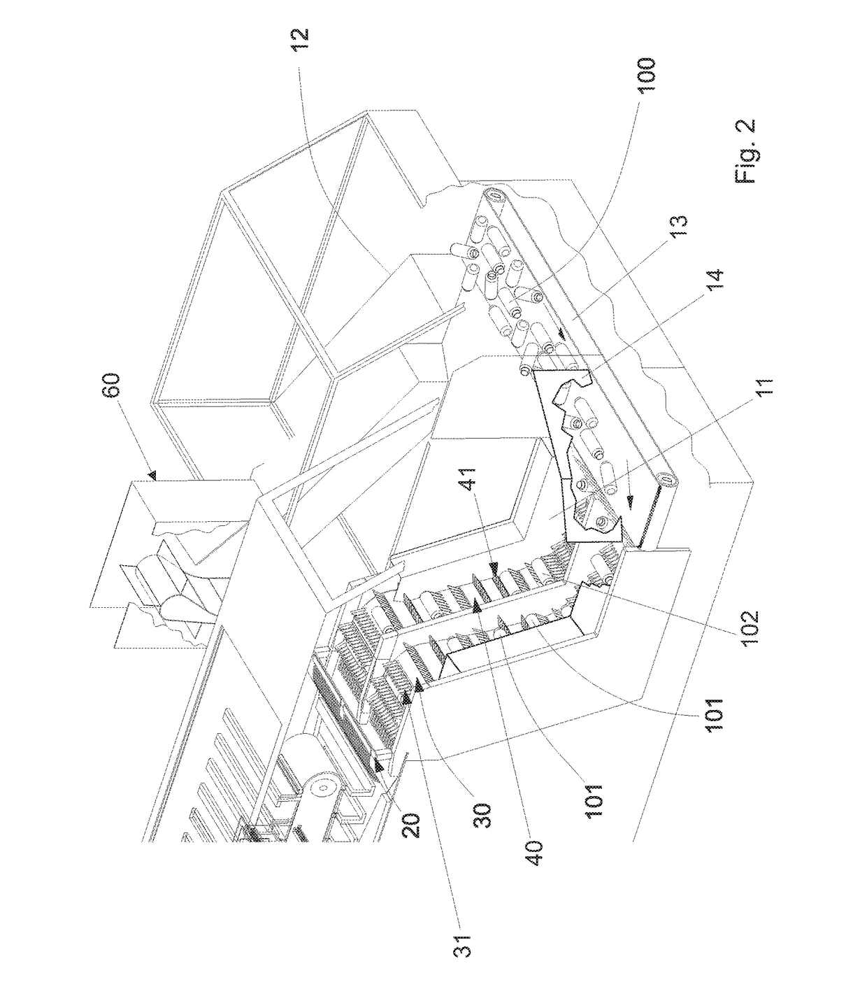
first embodiment
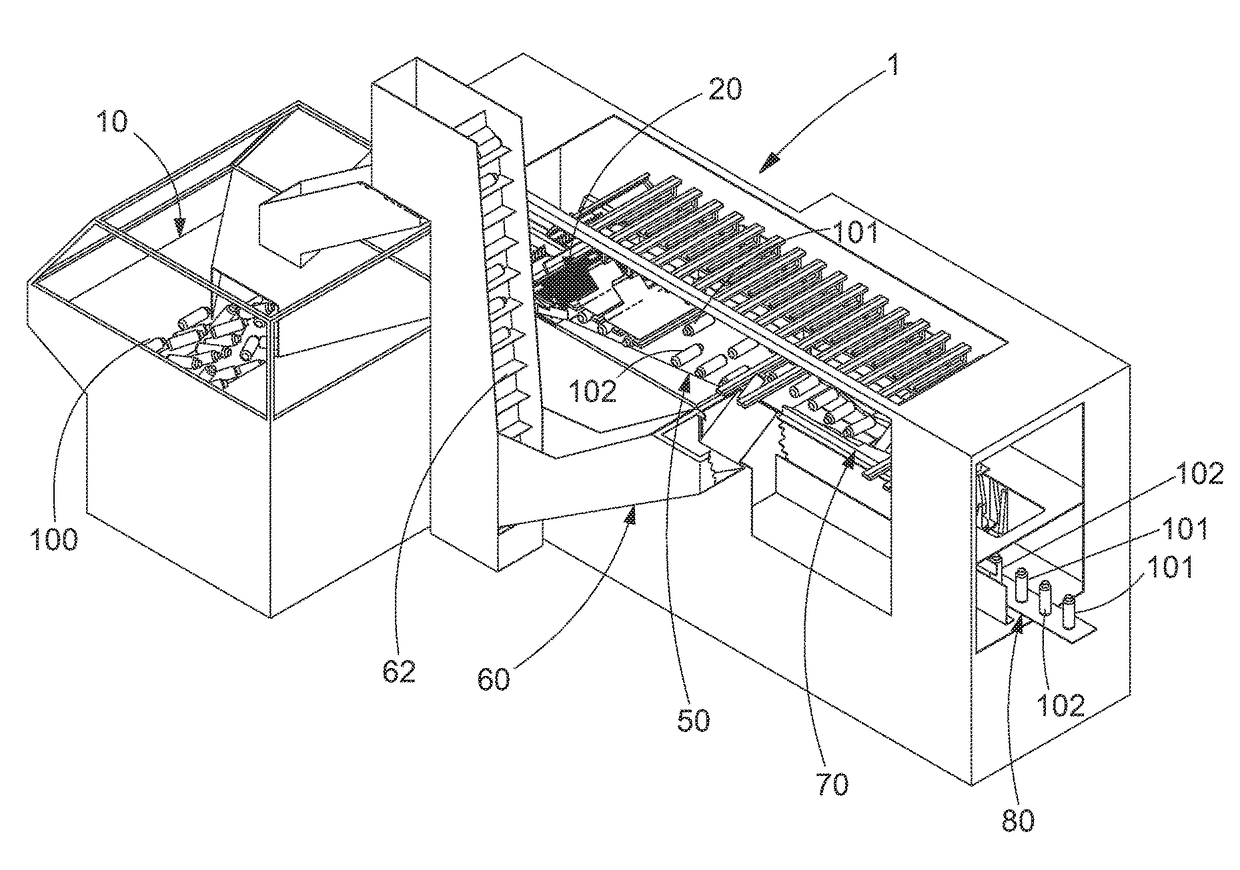
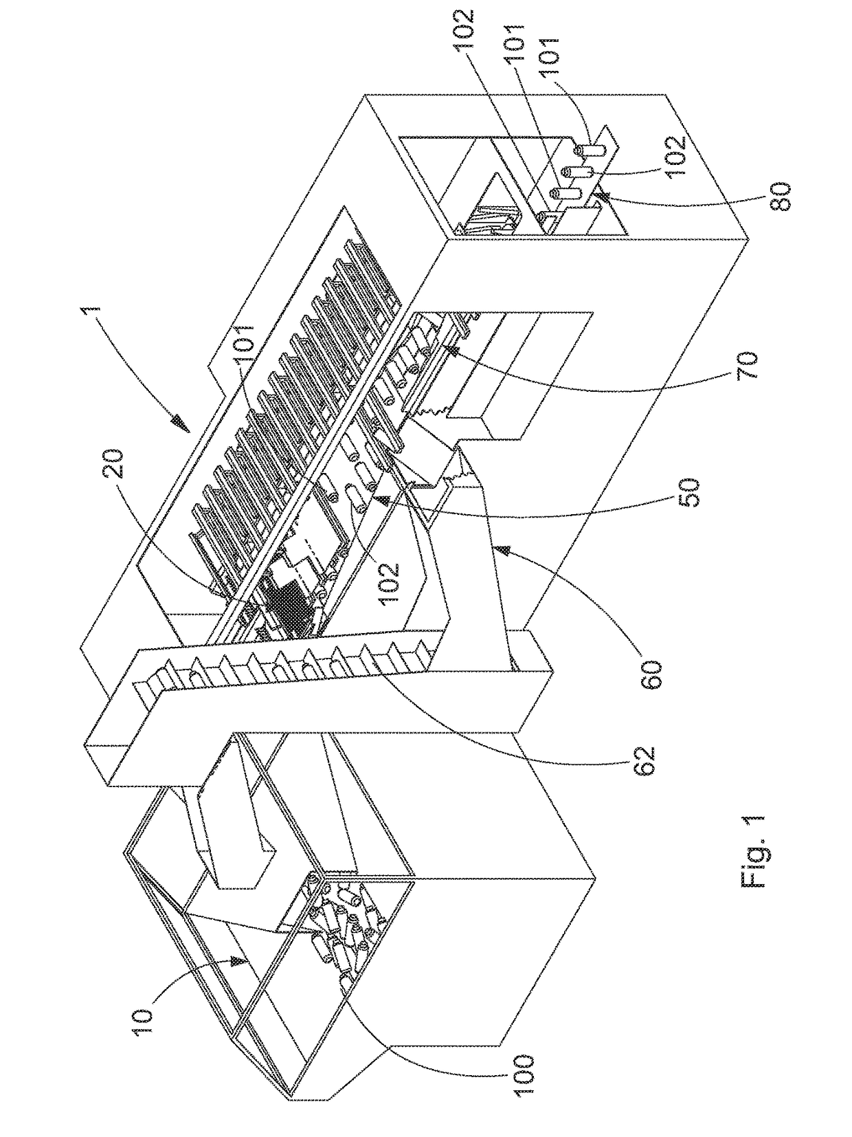
[0030]According to a first preferred embodiment of the machine, the first blades are horizontally aligned with respect to the second blades. That is to say, their position in height matches. This first embodiment generates the rejection of containers whenever the same pushing fin collects a first and a second container simultaneously. Whenever this happens, given that the width of passage decreases until it allows the passage of a single container, one of the two containers must be rejected.
[0031]In order to recover the rejected containers, the machine comprises a recovery station, which in turn has:[0032]a recovery ramp attached to the alignment station; and[0033]a recovery elevator configured to receive a first or a second container coming from the recovery ramp and return it to the hopper.
[0034]Said recovery ramp slopes down from an opening in the outer wall, located before the exit area, and ends at a recovery receptacle configured to supply the recovery elevator.
[0035]According...
second embodiment
[0090]This second embodiment does not generate the rejection of containers (101, 102), given that the same pushing fin can never collect a first (101) and a second container (102) simultaneously. The foregoing is because the delivery of containers of the first (31) and second blades (41) is carried out in an alternate manner.
[0091]The machine (1) comprises a positioning station (70) arranged at the end of the alignment station (50), FIG. 6, configured to position the first (101) and second containers (102) in a vertical position and aligned on an output conveyor belt (80). The containers (101, 102) are supported on their base and leave their neck at the upper end.
PUM
 Abstract
Description
Claims
Application Information
 - R&D
- Intellectual Property
- Life Sciences
- Materials
- Tech Scout
- Unparalleled Data Quality
- Higher Quality Content
- 60% Fewer Hallucinations
Browse by: Latest US Patents, China's latest patents, Technical Efficacy Thesaurus, Application Domain, Technology Topic, Popular Technical Reports.
© 2025 PatSnap. All rights reserved.Legal|Privacy policy|Modern Slavery Act Transparency Statement|Sitemap|About US| Contact US: help@patsnap.com