
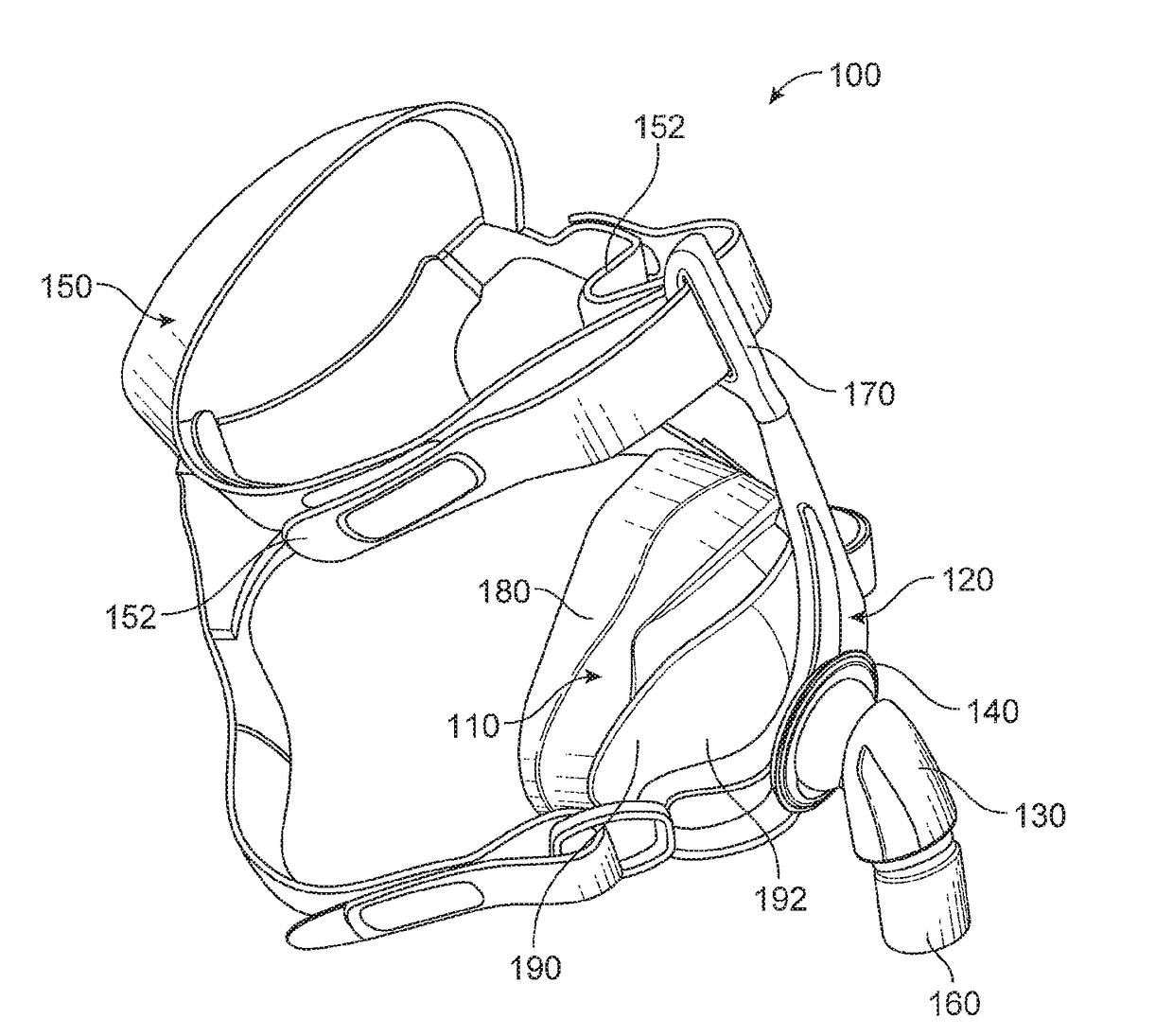
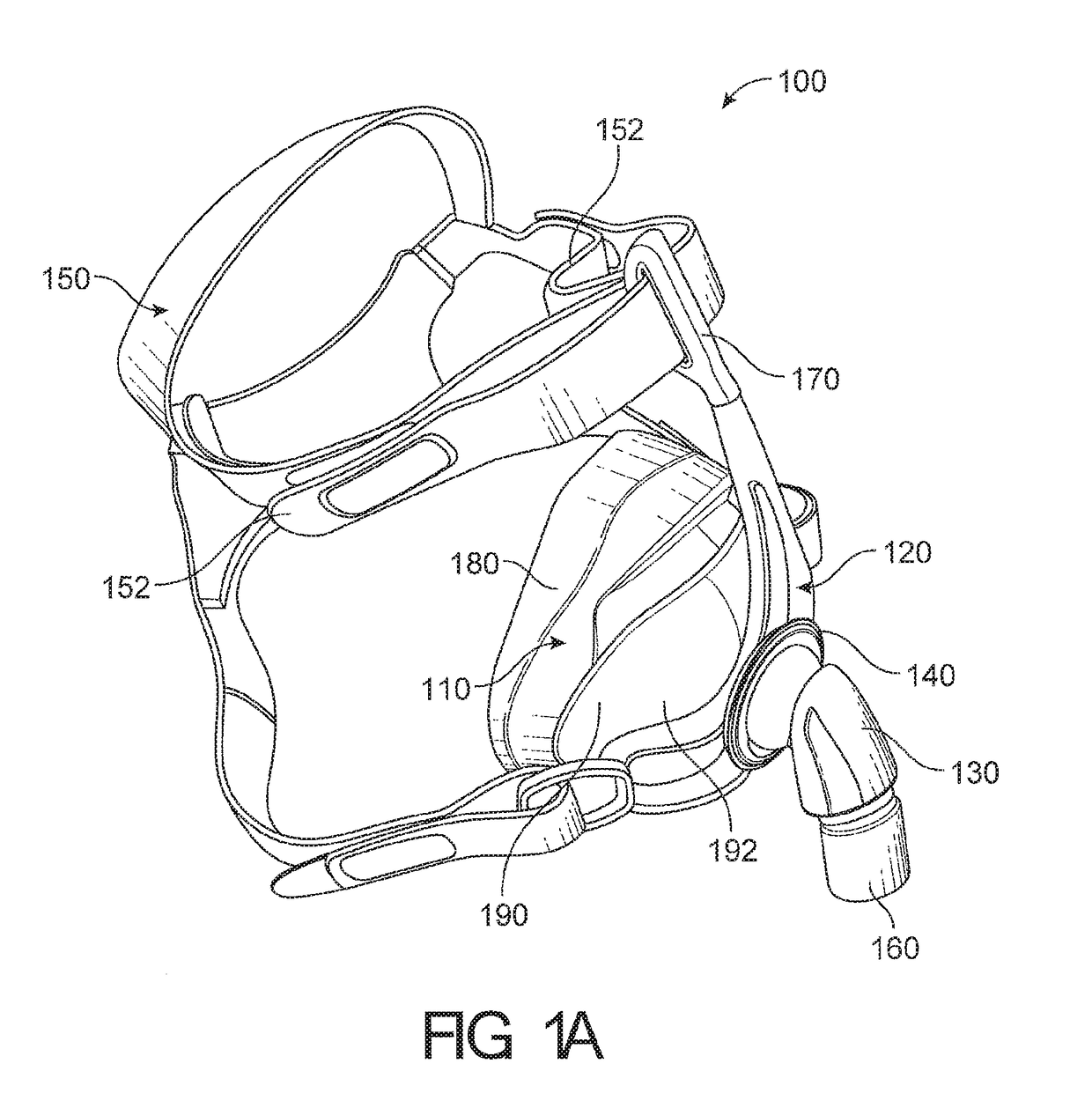
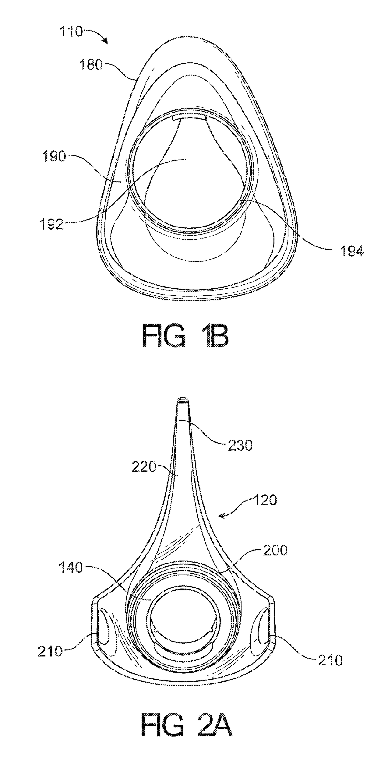
Respiratory mask and related portions, components or sub-assemblies

a mask and respiratory technology, applied in the field of respiratory masks, can solve the problems of limiting the useful life of the mask, difficult to remove and/or insert dirt, and difficult to remove dir

Active Publication Date: 2018-07-05
FISHER & PAYKEL HEALTHCARE LTD
View PDF3 Cites 41 Cited by
  • Summary
  • Abstract
  • Description
  • Claims
  • Application Information

AI Technical Summary

Benefits of technology

The patent is for a seal that has two thickened regions to prevent it from collapsing when it moves forward. This makes sure that the seal can perform its job effectively without getting damaged.

Problems solved by technology

Removal of this dirt may be difficult with the ball joint and socket connected.
The buildup of dirt and / or cleaning products may affect the hygiene of the mask and, thus, limit its useful lifetime.
The ball joint is usually permanently connected to its corresponding socket, or it is at least very difficult to remove and / or insert.
In some instances removal of the ball joint may require considerable force and may result in permanent damage to the mask.
This generally involves the manufacture of the entire mask, or at least the major mask components, in a range of sizes; which in turn increases the tooling and manufacturing costs associated with the mask.
Another problem associated with fixed mask sizes is that it is possible that a single fixed size mask is not suitable for a particular user's facial geometries.
Headgear for respiratory masks can traditionally be heavy, bulky, and hot to wear.
This can lead to discomfort for the user.
The venting system can become a source of discernable drafts and noise.
Drafts and noise can be annoying to both the user and / or their bed partner and may result in reduced compliance with the therapy.

Method used


Image

  • Respiratory mask and related portions, components or sub-assemblies
  • Respiratory mask and related portions, components or sub-assemblies
  • Respiratory mask and related portions, components or sub-assemblies

Examples


Embodiment Construction

[0145]Embodiments of systems, components and methods of assembly and manufacture will now be described with reference to the accompanying figures, wherein like numerals refer to like or similar elements throughout. Although several embodiments, examples and illustrations are disclosed below, it will be understood by those of ordinary skill in the art that the inventions described herein extends beyond the specifically disclosed embodiments, examples and illustrations, and can include other uses of the inventions and obvious modifications and equivalents thereof. The terminology used in the description presented herein is not intended to be interpreted in any limited or restrictive manner simply because it is being used in conjunction with a detailed description of certain specific embodiments of the inventions. In addition, embodiments of the inventions can comprise several novel features and no single feature is solely responsible for its desirable attributes or is essential to pra...


PUM


Abstract

A respiratory mask for providing positive pressure therapy and a bias-flow venting system configured to reduce discernable draft generated by exhausted air are disclosed herein. The respiratory mask has a ball jointed elbow, one or more detachable forehead pieces and a headgear with a spacer fabric region. The elbow is configured to be removable when oriented to a predetermined position. The forehead pieces are provided in one or more sizes. The spacer fabric region having two or more layers wherein the raw edges are turned to the inside of the layers. The seal having improved seal performance and accommodating a wider variety of facial geometries. The bias-flow system having a tube and exhaust holes radially aligned on a bead of the tube. The bias-flow system also having an annular component exhaust holes and a shroud having a plenum chamber around the exhaust holes.

Description

INCORPORATION BY REFERENCE TO PRIORITY APPLICATIONS[0001]This application is related to and claims priority from U.S. Provisional Patent Application Nos. 62 / 041,236, filed Aug. 25, 2014, 62 / 096,481, filed Dec. 23, 2014, 62 / 041,234, filed Aug. 25, 2014 and 62 / 041,262, filed Aug. 25, 2014, the entireties of which are hereby incorporated by reference herein and made a part of the present disclosure.BACKGROUNDField[0002]The present disclosure generally relates to respiratory masks that cover at least one of a nose and a mouth of a user to supply respiratory gas under positive pressure. More particularly, certain aspects of the present disclosure relate to a respiratory mask with one or more of a removable ball jointed elbow, one or more detachable forehead pieces, and spacer fabric headgear. The disclosure also relates to seal cushion arrangements.Description of Related Art[0003]Respiratory masks can be used to provide respiratory gases to a user under positive pressure. In configuratio...

Claims


Application Information

Patent Timeline
IPC IPC(8): A61M16/06A61M16/08
CPCA61M16/0622A61M16/0694A61M16/0825A61M16/0633A62B18/08A61M16/0683A61M16/0875A61M16/0611A61M16/0616A61M2202/0225A61M2202/0085A61M16/06
Inventor OLSEN, GREGORY JAMESBORNHOLDT, MELISSA CATHERINEMARTIN, CAMPBELL NEIL ADDISONSPEAR, TONY WILLIAMMITTERMEIER, SIMONROSE, HAMISH JOSHUABETTERIDGE, MAX LEONNIGHTINGALE, CHRISTOPHER EARLPEDERSEN, MATTHEW JAMESJOHNSON, SOPHIA ADELEARROWSMITH, MARK JOHN
Owner FISHER & PAYKEL HEALTHCARE LTD
Learn More