Head-up display device

Inactive Publication Date: 2018-06-28
DENSO CORP
View PDF4 Cites 11 Cited by
  • Summary
  • Abstract
  • Description
  • Claims
  • Application Information

AI Technical Summary

Benefits of technology

The present invention is about a head-up display (HUD) device that can prevent the temperature of its projector from rising while maintaining the brightness of its virtual image display. The inventors found that external light, such as sunlight, can enter the HUD device and make the projector hot. The invention proposes the use of a phase shifter to efficiently shield the external light and reduce the temperature of the projector. The phase shifter is placed between the polarizer and the projector or the polarizer and the projector's optical path. This placement ensures that the phase shifter intersects with the direction of the polarizer and the direction of the external light, making it possible to change the direction of the partially polarized light and efficiently shield it from the projector while transmitting the light of the image from the projector to the projection member. The invention, therefore, provides a solution to prevent projector temperature rise while maintaining virtual image brightness.

Problems solved by technology

There are cases where external light such as sunlight enters the HUD device and reaches the projector, thereby increasing the temperature of the projector.

Method used


Image

  • Head-up display device
  • Head-up display device
  • Head-up display device

Examples


first embodiment

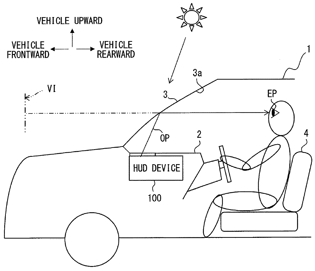
[0022]As shown in FIG. 1, an HUD device 100 according to a first embodiment of the present disclosure is mounted in a vehicle 1, and housed in an instrument panel 2. The HUD device 100 projects an image on a windshield 3 as a projection member of the vehicle 1. The light of the image is reflected by the windshield 3, so that the HUD device 100 virtually displays an image to be viewable by an occupant of the vehicle 1. That is, the light of the image reflected by the windshield 3 reaches an eye point EP of the occupant inside the vehicle 1, and the occupant perceives the light of the image as a virtual image VI. Accordingly, the occupant can visually recognize various kinds of information through the virtual image VI. The various kinds of information virtually displayed as the image include, for example, vehicle state values such as a vehicle speed and a fuel remaining amount, or navigation information such as road information and vision auxiliary information.

[0023]The windshield 3 o...

second embodiment

[0060]As shown in FIGS. 8 to 9, a second embodiment of the present disclosure is a modification of the first embodiment. The differences of the second embodiment from the first embodiment will be mainly described.

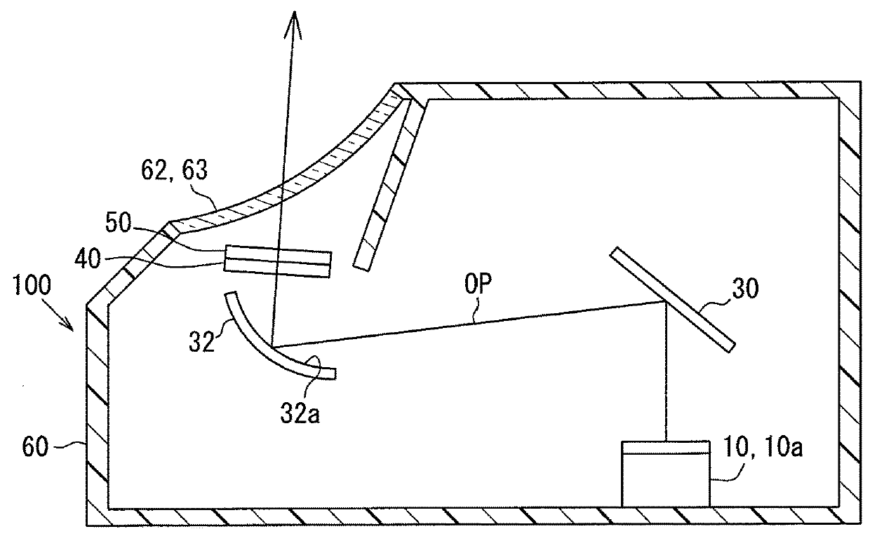
[0061]As shown in FIG. 8, a retardation plate 250 in an HUD device 200 according to the second embodiment is disposed between the projector 10 and a polarizing plate 240 on the optical path OP, and is a phase shifter formed like a flat plate. More specifically, the retardation plate 250 is disposed between the concave mirror 32 and the polarizing plate 240. The retardation plate 250 has a property of changing the polarization direction of transmitted light by producing a phase difference, as in the first embodiment. By the setting of the direction (hereinafter referred to as a fast axis direction DF) of a fast axis 251 substantially orthogonal to a slow axis 252, the light of an image transmitted through the retardation plate 250 changes the polarization direction, and ente...


PUM


Abstract

A head-up display device is mounted in a vehicle and virtually displays an image to be viewable by an occupant by projecting the image on a light-transmissive projection member. The head-up display device includes a projector that projects the image as light polarized in a direction of a polarization axis, a polarizer that is disposed on an optical path of the light of the image and has a property of transmitting light polarized along a transmission axis, and a phase shifter that is disposed between the polarizer and the projection member on the optical path and has a property of changing a polarization direction of transmitted light by producing a phase difference. A fast axis direction of the phase shifter intersects with a direction corresponding to the polarization axis, a direction corresponding to the transmission axis, and a direction corresponding to S polarization of the projection member.

Description

CROSS REFERENCE TO RELATED APPLICATION[0001]This application is based on Japanese Patent Application No. 2015-129174 filed on Jun. 26, 2015, the disclosure of which is incorporated herein by reference.TECHNICAL FIELD[0002]The present disclosure relates to a head-up display device (hereinafter abbreviated as an HUD device) that is to be mounted in a vehicle and to virtually display an image to be viewable by an occupant.BACKGROUND ART[0003]Conventionally, there has been known an HUD device that is mounted in a vehicle and virtually displays an image to be viewable by an occupant. An HUD device disclosed in Patent Literature 1 projects an image on a light-transmissive projection member. The HUD device includes a projector that projects an image as light polarized in a direction corresponding to a polarization axis, a polarizer that is disposed on an optical path formed by the light of the image and has a property of transmitting light polarized along a transmission axis, and a phase s...

Claims


Application Information

Patent Timeline
IPC IPC(8): G02B27/01B60K35/00G02B5/30
CPCG02B27/0101B60K35/00G02B5/3083G02B5/3025B60K2350/2052B60K2350/2069B60K2350/2056G02B2027/0118G02B27/286G02B27/01B60K2360/334B60K2360/347B60K2360/349
Inventor YOKOE, JUNYANAMBARA, TAKAHIRO
Owner DENSO CORP
Why Eureka
Try Eureka