
System for monitoring the activity status of at least one venue

a technology for monitoring the activity status of at least one venue, applied in the field of information technology, can solve the problems of large amount of information currently available on an establishment, static, and fails to reflect the dynamic nature of such establishments, and achieve the effect of convenient configuration and readily scalabl

Inactive Publication Date: 2018-06-21
SPOTBEAT INC
View PDF7 Cites 4 Cited by
  • Summary
  • Abstract
  • Description
  • Claims
  • Application Information

AI Technical Summary

Benefits of technology

The present invention provides a venue monitoring system that is easy to set up and expand. This system is designed to be flexible and adaptable to different needs and situations.

Problems solved by technology

Nonetheless, the majority of information that is currently available on an establishment, whether provided directly from the establishment or crowdsourced through patrons, is static.
In other words, much of the available information on a business remains largely unchanged over time and thereby fails to reflect the dynamic nature of such establishments.
As a result, the consuming public frequently decides whether to visit an establishment using an insufficient amount of information, much of which is often stale or inexact.
Most notably, there is currently no effective means to compile and evaluate, in real time, crowd-based information relating to selected establishments within a particular geographic region.
In the absence of such information, a potential patron is unable discern the real-time popularity and social atmosphere of an establishment, which is often a critical factor when rendering a decision where to visit.
However, it has been found that use of such a check-in feature provides limited value in assessing the overall popularity status of certain establishments.
Additionally, the check-in information is most commonly restricted to the members of an exclusive network.

Method used


Image

  • System for monitoring the activity status of at least one venue
  • System for monitoring the activity status of at least one venue
  • System for monitoring the activity status of at least one venue

Examples


Embodiment Construction

Venue Monitoring System 11

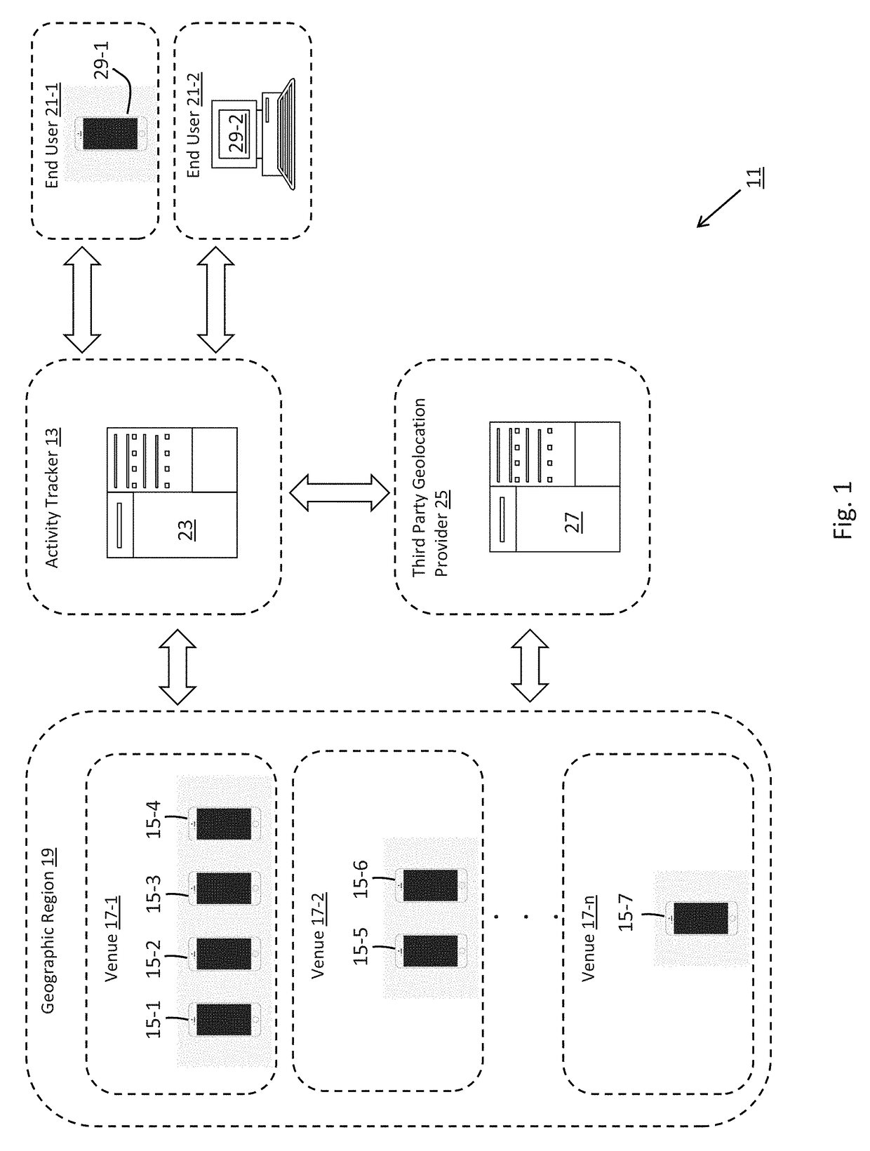
[0023]Referring now to FIG. 1, there is shown a simplified schematic representation of a system for monitoring the activity status of at least one venue, the system being constructed according to the teachings of the present invention and identified generally by reference numeral 11. As will be described in detail below, venue monitoring system 11 is designed to track the presence of active mobile devices within selected venues in order to establish a real-time activity status for each venue that is based, in part, on detected crowd size.

[0024]As can be seen, venue monitoring system 11 comprises an activity tracker 13 that monitors the use of mobile devices 15 in selected venues 17-1 thru 17-n within a broader geographic region 19. Using such information, activity tracker 13 designates a real-time activity status, or popularity level, for each venue 17 that, in turn, can be retrieved and evaluated by interested parties (e.g., potential patrons amongst the c...


PUM


Abstract

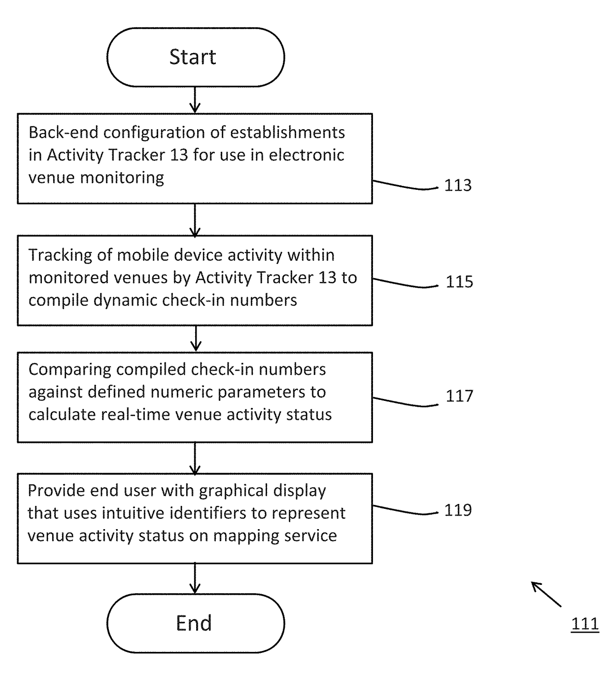
A venue monitoring system includes an activity tracker that fetches geolocation data from active mobile devices in order to estimate real-time crowd sizes at certain venues, such as restaurants, bars, nightclubs and the like. By comparing detected crowd sizes against a fixed numerical parameter, such as a predefined occupancy load, the activity tracker is able to designate a real-time activity status for each monitored venue that is indicative of its social atmosphere. End users in electrical communication with the activity tracker are able to intuitively discern the relative popularity of a plurality of venues within a common geographic region using a designated software application. As a critical component of the application functionality, a graphical display is provided to the end user that represents the activity status of monitored venues by integrating dynamic indicators, which vary in size, color and pulse rate, into a web mapping service.

Description

FIELD OF THE INVENTION[0001]The present invention relates generally to information technology and, more particularly, to systems and methods for providing electronic data relating to notable aspects of commercial businesses.BACKGROUND OF THE INVENTION[0002]Information technology (IT) relates to the use of computers to compile, transmit, and receive information on a seemingly limitless range of subjects. With the advancement of information technology as well as the ubiquitous use of mobile devices, the consuming public has become increasingly reliant upon electronic data when evaluating commercial businesses.[0003]In particular, there is currently available a growing amount of relevant information on commercial establishments that provide food, drink and entertainment services, such as restaurants, bars, nightclubs and the like. By evaluating such information, a member of the consuming public can more effectively decide whether to visit certain establishments.[0004]Basic information ...

Claims


Application Information

Patent Timeline
Patent Type & Authority Applications(United States)
IPC IPC(8): H04W4/02H04L29/08G06Q50/00G06Q30/02
CPCH04W4/021H04L67/22G06Q30/0201G06Q50/01H04L67/20H04L67/53H04L67/535
Inventor BEAL, ALEXANDER E.
Owner SPOTBEAT INC
Learn More