Support device and user terminal
a support device and user terminal technology, applied in the field of support devices and user terminals, to achieve the effect of facilitating user autosuggestion and eliminating the need for external power supply
- Summary
- Abstract
- Description
- Claims
- Application Information
AI Technical Summary
Benefits of technology
Problems solved by technology
Method used
Image

Examples
example 1
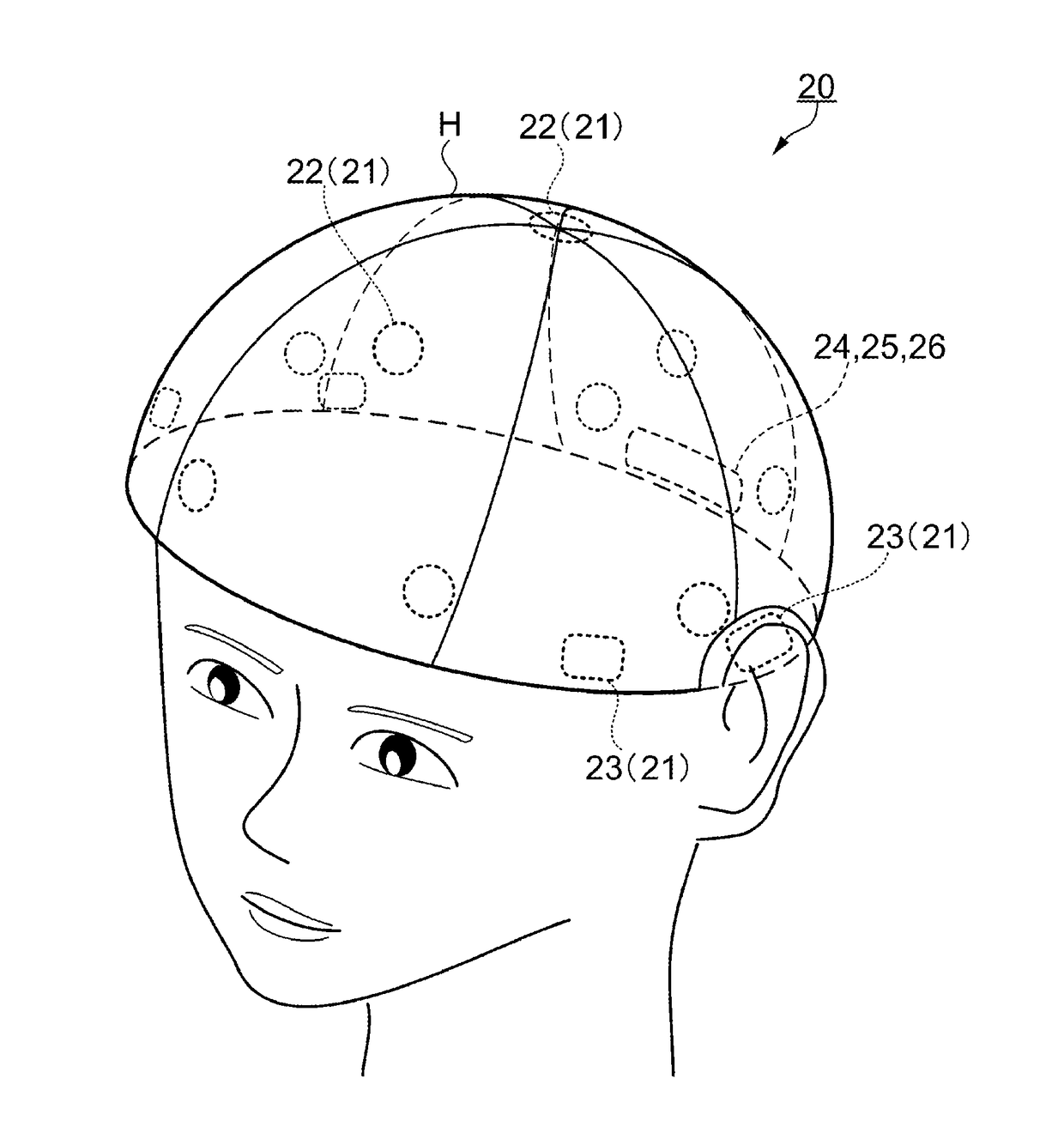
[0062]FIG. 3 is a schematic view showing a user terminal according to Example 1. As shown in FIG. 3, a user terminal 20 according to Example 1 is in the form of a head cap. The user terminal 20 has a substantially hemispherical shape wearable on the head H of the user. FIG. 3 shows an example in which the detection terminal unit 22 of the living body contact unit 21 is placed at positions corresponding to the frontal lobes, temporal lobes, parietal lobes, and occipital lobes, with the stimulus terminal unit 23 of the living body contact unit 21 being placed on the temples and the ears, and with the communication unit 24, the control unit 25, and the power supply unit 26 being placed on the back of the head. However, the placement of each unit is not limited to this.
[0063]The head cap-type user terminal 20 shown in FIG. 3 covers the entirety of the head H of the user and therefore can be worn in a stable state. Also, the detection terminal units 22 and the stimulus terminal units 23 ...
example 2
[0064]FIG. 4 is a schematic view showing a user terminal according to Example 2. As shown in FIG. 4, a user terminal 30 according to Example 2 is in the form of a hair accessory. The user terminal 30 is formed in a substantially C-shape with elasticity, for example, using plastics or the like as a base material, and is worn by being put over an area from the temporal regions (behind the ears) to the top of the head of the user. The detection terminal unit 22 and the stimulus terminal unit 23, the communication unit 24, the control unit 25, and the power supply unit 26 are placed on the side that comes in contact with the head H of the user along the substantially C-shape.
[0065]The hair accessory-type user terminal 30 shown in FIG. 4 looks like an accessory and therefore its appearance gives no inadequate impression even if the user terminal 30 is worn outdoors as well as indoors. However, since the user terminal 30 is not in a shape that covers the entirety of the head H of the user...
example 3
[0066]FIG. 5 is a schematic view showing a user terminal according to Example 3. As shown in FIG. 5, a user terminal 31 according to Example 3 is in the form of a wig. The detection terminal unit 22 and the stimulus terminal unit 23, the communication unit 24, the control unit 25, and the power supply unit 26 are placed on the inner side (side that comes in contact with the head H of the user) of the user terminal 31.
[0067]It can be said that the user terminal 31 is the head cap-type user terminal 20 according to Example 1 with hair arranged on the outside. Since the user terminal 31 covers the entirety of the head H of the user, as in Example 1, the detection terminal unit 22 and the stimulus terminal unit 23 can be placed respectively at optimum positions. Also, the user terminal 31 is in the form of a wig and therefore can be worn regardless of indoors or outdoors.
PUM
 Abstract
Description
Claims
Application Information
 - R&D
- Intellectual Property
- Life Sciences
- Materials
- Tech Scout
- Unparalleled Data Quality
- Higher Quality Content
- 60% Fewer Hallucinations
Browse by: Latest US Patents, China's latest patents, Technical Efficacy Thesaurus, Application Domain, Technology Topic, Popular Technical Reports.
© 2025 PatSnap. All rights reserved.Legal|Privacy policy|Modern Slavery Act Transparency Statement|Sitemap|About US| Contact US: help@patsnap.com