Antenna matching circuit, antenna circuit, front-end circuit, and communication apparatus
a technology of antenna circuit and antenna, applied in the direction of resonant antenna, substantially flat resonant elements, elongated active element feed, etc., can solve the problems of limited range of impedance for achieving matching, and limited space in which cellular phone terminals may be mounted
- Summary
- Abstract
- Description
- Claims
- Application Information
AI Technical Summary
Benefits of technology
Problems solved by technology
Method used
Image
Examples
first embodiment
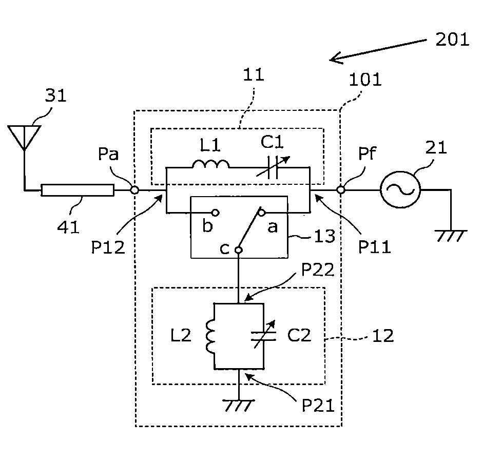
[0066]FIG. 1 is a circuit diagram of an antenna circuit 201 according to the first embodiment. The antenna circuit 201 includes an antenna matching circuit (antenna tuner) 101, a power feed circuit 21, a transmission line 41, and an antenna 31.
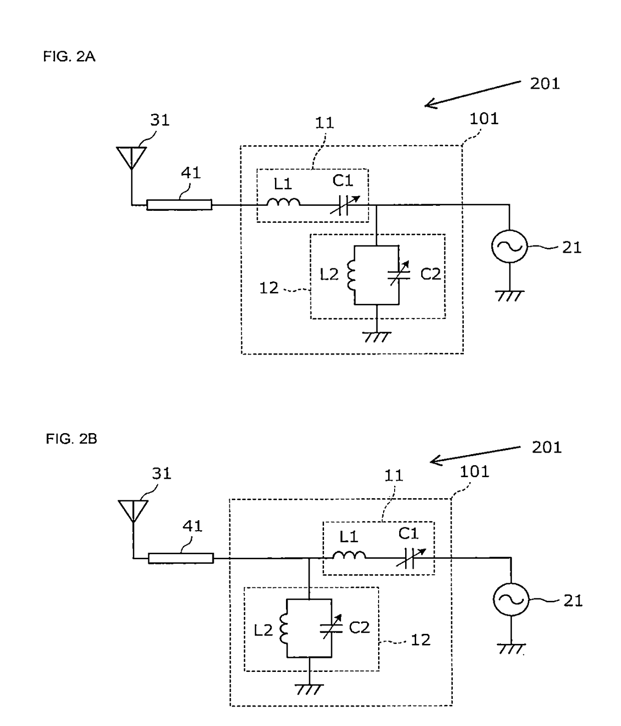
[0067]The antenna matching circuit 101 includes a first circuit 11 that is connected in series between a power feed port Pf and an antenna port Pa, a second circuit 12 that is connected in parallel between the power feed port Pf and the ground or between the antenna port Pa and the ground, and a switch 13.
[0068]The first circuit 11 is a circuit in which a first variable capacitance element C1 is connected in series with a first inductor L1. The second circuit 12 is a circuit in which a second variable capacitance element C2 is connected in parallel with a second inductor L2.
[0069]A first end P11 of the first circuit 11 is connected to the power feed port Pf, and a second end P12 of the first circuit 11 is connected to the antenna port Pa. A fi...
second embodiment
[0089]In the second embodiment, an antenna circuit 202 is illustrated that includes two antennas and two power feed circuits.
[0090]FIG. 7 is a circuit diagram of the antenna circuit 202 according to the second embodiment. The antenna circuit 202 includes a low band antenna circuit and a mid / high band antenna circuit. The mid / high band antenna circuit includes a second power feed circuit 22, a second transmission line 42, and a second antenna 32. The low band antenna circuit includes an antenna matching circuit 101, a first power feed circuit 21, a low pass filter 51, a first transmission line 41, and a first antenna 31. The low pass filter 51 is inserted between the antenna matching circuit and the first transmission line 41, that is, on the antenna side with respect to the antenna matching circuit 101. The antenna matching circuit 101 and the low pass filter 51 are configured as one antenna matching circuit module 112.
[0091]Here, a low band is an example of “first communication fre...
third embodiment
[0098]In a third embodiment, an antenna circuit 203 is illustrated that includes two antennas and two power feed circuits.
[0099]FIG. 9 is a circuit diagram of the antenna circuit 203 according to the third embodiment. The antenna circuit 203 includes a low band antenna circuit and a mid / high band antenna circuit. The mid / high band antenna circuit includes a second power feed circuit 22, a high pass filter 52, a second transmission line 42, and a second antenna 32. The low band antenna circuit includes an antenna matching circuit 101, a first power feed circuit 21, a low pass filter 51, a first transmission line 41, and a first antenna 31.
[0100]The cutoff frequency of the high pass filter 52 is between a low band and a mid / high band. That is, the high pass filter 52 allows a mid / high band signal to pass therethrough and blocks a low band signal. As a result, even when a transmission wave (fundamental) emitted from the first antenna (low band antenna) 31 reaches the second antenna (mi...
PUM
 Abstract
Description
Claims
Application Information
 - R&D
- Intellectual Property
- Life Sciences
- Materials
- Tech Scout
- Unparalleled Data Quality
- Higher Quality Content
- 60% Fewer Hallucinations
Browse by: Latest US Patents, China's latest patents, Technical Efficacy Thesaurus, Application Domain, Technology Topic, Popular Technical Reports.
© 2025 PatSnap. All rights reserved.Legal|Privacy policy|Modern Slavery Act Transparency Statement|Sitemap|About US| Contact US: help@patsnap.com


