
Butterfly valve for bleeding a compressor for an aircraft turbine engine

a compressor and valve technology, applied in the field of valves for bleeding compressors, can solve the problems of low or high-pressure compressor air supply quantity, low or high-pressure compressor mass flow rate, and inability to adjust,

Active Publication Date: 2018-05-24
SN DETUDE & DE CONSTR DE MOTEURS DAVIATION S N E C M A
View PDF11 Cites 3 Cited by
  • Summary
  • Abstract
  • Description
  • Claims
  • Application Information

AI Technical Summary

Benefits of technology

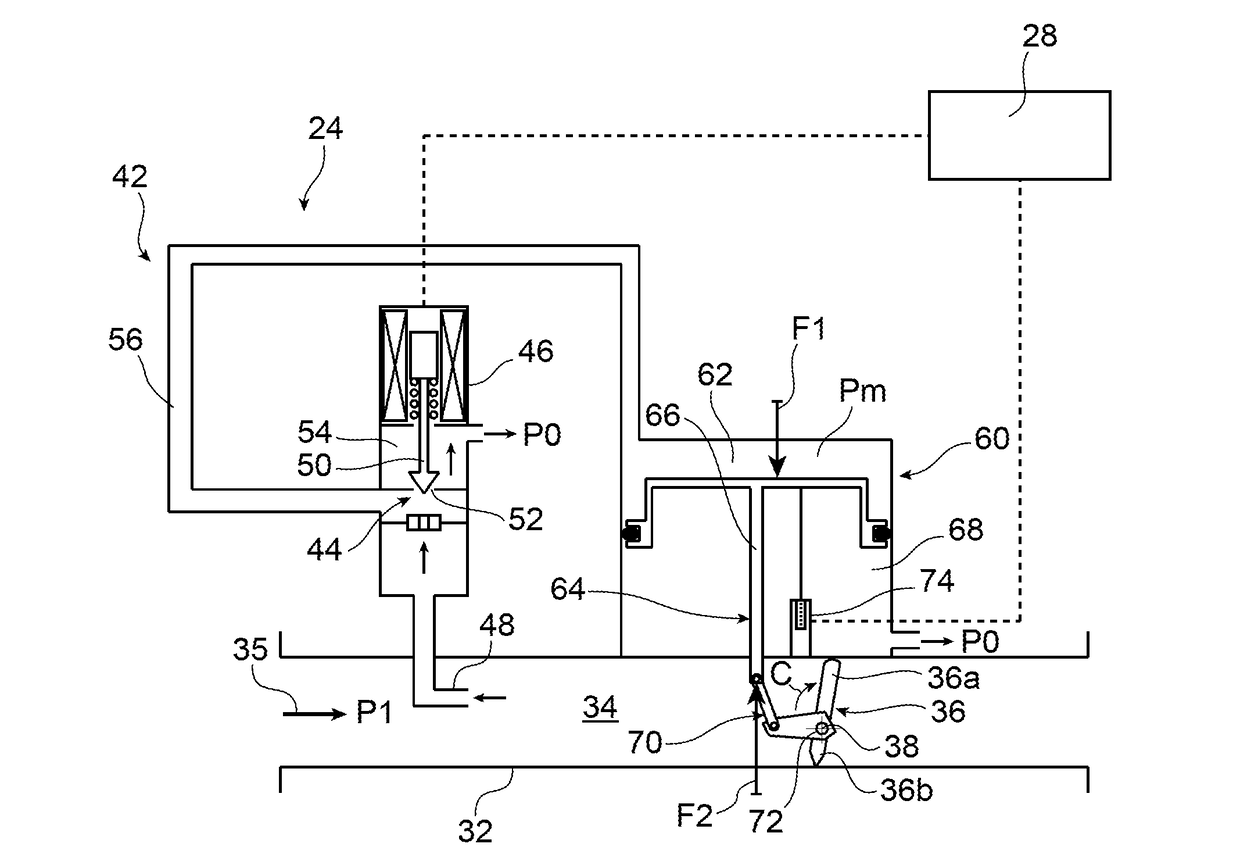
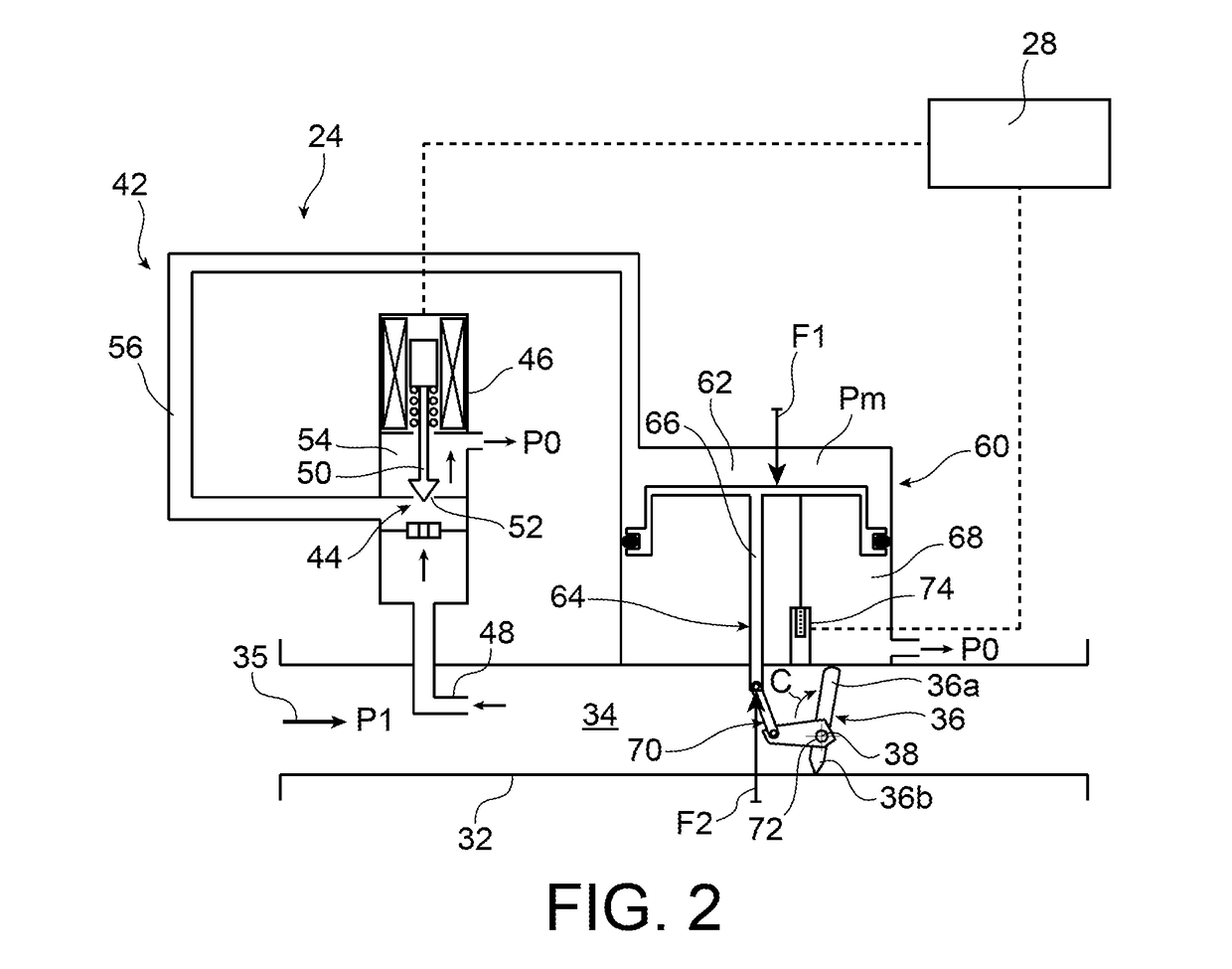
The invention is a new design for a valve used in turbine engines that reduces the time it takes to open and close. This is achieved by using an aerodynamic force, instead of a spring, to provide the second mechanical force needed to move the valve. The aerodynamic force is proportional to the opening angle of the valve, so it increases as the valve approaches its maximum opening. This design also allows for a quicker response time in case of an air pressure surge, which can help to restore stability to the turbine engine more quickly.

Problems solved by technology

Indeed, under certain flight conditions such as for example the aircraft descent phase, the quantity of air supplied by the low or high-pressure compressor, i.e. the mass flow rate of the air supplied by the compressor, may be too high to ensure satisfactory operation of the turbine engine.
This second force thereby exhibits no adjustability, unlike the first pressure force, the adjustment whereof makes it possible to actuate the piston in one direction or in the other, resulting in opening or closure of the butterfly.
However, this first design has a number of drawbacks including significant frictions observed within the valve, as well as the compressibility of the air in the cylinder housing the dual-acting piston.
These drawbacks, particularly air compressibility, induce non-linear phenomena impeding the response stability of the control device.
First of all, the response speed of the control device remains affected by the aerodynamic torque applied by the air onto the butterfly, and which impedes the opening thereof.
Outside this range of values, the second mechanical force may prove to be too high or too low, and thereby impede the response speed and stability of the control device.
This proves to be problematic since the pressure within the compressor is liable to vary in large proportions, sometimes by up to a factor of fifty.
This pressure in the compressor stream having a direct impact on the intensity of the first pressure force, operating scenarios may thereby arise wherein the design of the spring proves to be unsuitable for supplying a second mechanical force with a suitable intensity.

Method used


Image

  • Butterfly valve for bleeding a compressor for an aircraft turbine engine
  • Butterfly valve for bleeding a compressor for an aircraft turbine engine
  • Butterfly valve for bleeding a compressor for an aircraft turbine engine

Examples


Embodiment Construction

[0011]The aim of the invention is that of at least partially remedying the drawbacks mentioned above, relative to the embodiments of the prior art.

[0012]For this purpose, the invention relates to a butterfly valve for bleeding a compressor for an aircraft turbine engine, the valve comprising a valve body defining a channel through which the air from the compressor is intended to enter, a butterfly rotatably mounted inside the channel about an axis of butterfly rotation, as well as a device for controlling the angular position of the butterfly, the control device comprising a mobile actuation member connected to the butterfly by linking means, the actuation member being designed to be subjected:[0013]to a first adjustable pressure force applied by air from the compressor, for example extracted directly in the primary stream of the compressor or possibly in said channel, the first adjustable pressure force returning the butterfly to a closed position; and[0014]to a second mechanical f...


PUM


Abstract

The invention relates to a butterfly valve (24) for bleeding a compressor for an aircraft turbine engine, the valve including a valve body (32), a butterfly (36), and a device (42) for controlling the angular position of the butterfly, the device (42) including a mobile actuation member (64) connected to the butterfly by a link (70), the member (64) being subjected: to a first adjustable pressure force (F1) applied by air from the compressor, the first force (F1) returning the butterfly (36) to a closed position; and to a second mechanical force (F2) returning the butterfly (36) to an open position, and coming from an aerodynamic torque (C) applied by the air to the butterfly (36), of which the axis of rotation (38) is off-centre relative to the butterfly.

Description

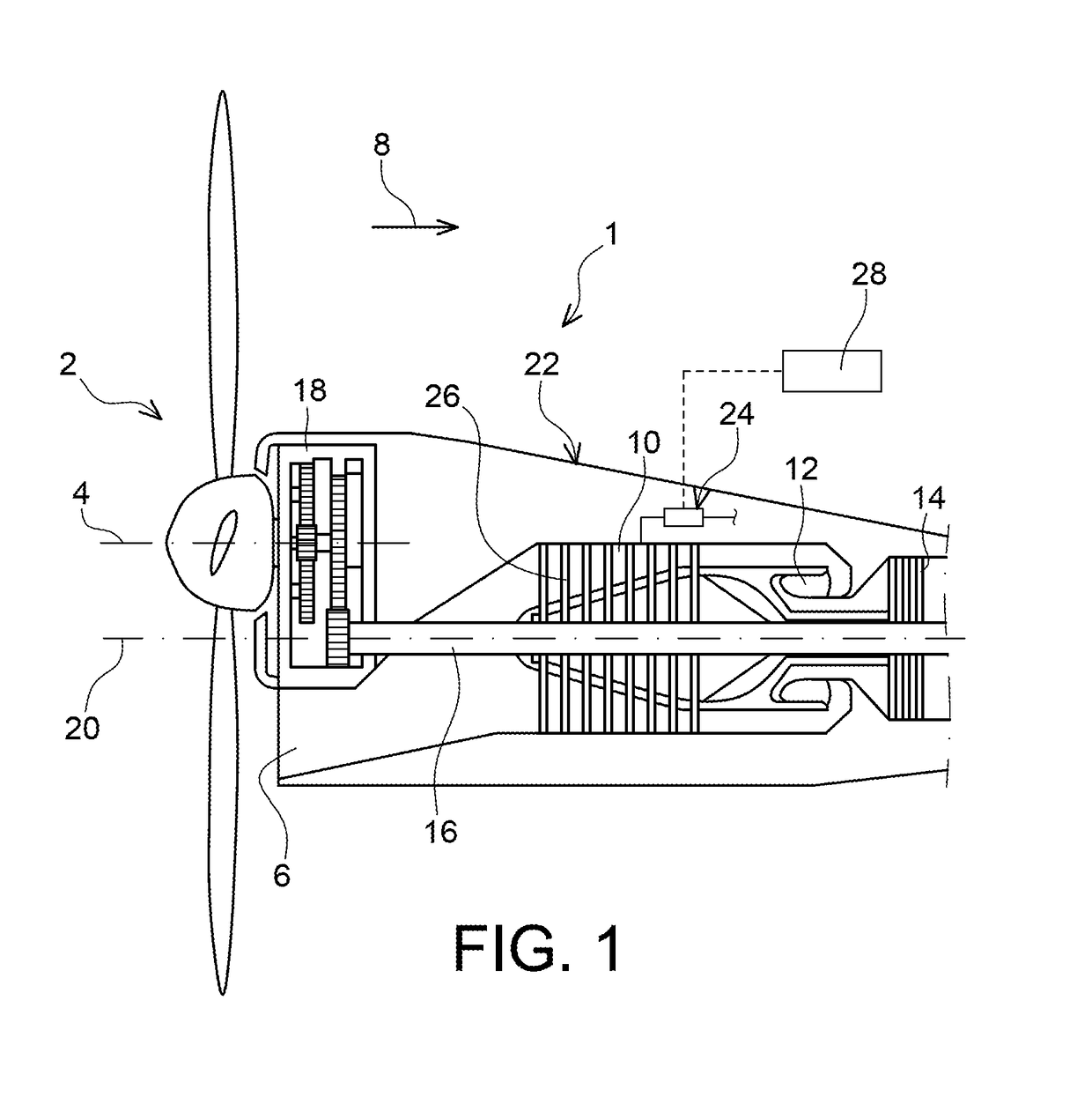
FIELD OF THE INVENTION[0001]The present invention relates to the field of aircraft turbine engines, and more particularly to valves for bleeding a compressor fitted in such a turbine engine.[0002]The term bleeding an aircraft turbine engine compressor denotes momentarily diverting a portion of the air flow passing through the compressor, for example towards an air stream external to the compressor, so as to limit the mass flow rate of the air supplied by the compressor. In this regard, it is noted that a pressure bleed relates to a scenario where the bleed has the side-effect of reducing the air pressure in the compressor, but as a general rule, the bleed first of all has the effect of limiting or reducing the mass flow rate of the air at the outlet of said compressor.[0003]The invention applies in particular to turboprops, but also to other types of aircraft turbine engines such as turbojets, preferably double-flow and double-body.STATE OF THE RELATED ART[0004]In aircraft turbine e...

Claims


Application Information

Patent Timeline
IPC IPC(8): F02C9/18F04D27/02F16K1/22
CPCF02C9/18F04D27/0215F16K1/221F05D2220/323F05D2270/331F05D2270/3061F02C6/08F04D27/023
Inventor JOUDAREFF, ARNAUDMOUTON, PIERRE CHARLESWAISSI, BELLAL
Owner SN DETUDE & DE CONSTR DE MOTEURS DAVIATION S N E C M A
Learn More