Screw Compressor and a Compressor Body Thereof

a screw compressor and compressor body technology, applied in the field of screw compressors, can solve the problems of reducing affecting the operation process of the compressor, and the rotor chamber is not sufficiently cool, so as to reduce the overall noise of the compressor and avoid excessive discharge temperature

Active Publication Date: 2018-05-17
GREE ELECTRIC APPLIANCES INC
View PDF5 Cites 0 Cited by
  • Summary
  • Abstract
  • Description
  • Claims
  • Application Information

AI Technical Summary

Benefits of technology

[0014]As can be seen from the aforementioned solution, a coolant after entering the suction inlet, first enters the cooling chamber, and then enters the rotor chamber via the air inlet. By means of such structural design, the coolant subject to air suction forms a flow in the cooling chamber. As the coolant subject to air suction has a lower temperature, and the outer wall of the rotor chamber has a higher temperature, by means of a coolant flow, the rotor chamber can be sufficiently cooled to avoid an excessively high discharge temperature. Moreover, the coolant flow can also sufficiently absorb noise and vibration radiated from the rotor chamber, thus further reduce overall machine noise of the compressor.
[0015]In order to realize the aforementioned second object, the present application further provides a screw compressor comprising a compressor body, a spool valve, a male rotor, a female rotor and a filter element, the compressor body is the compressor body of the aforementioned any technical solution, the spool valve is disposed at the spool chamber, the male rotor is disposed at the male rotor chamber, and the female rotor is disposed at the female rotor chamber. As the aforementioned compressor body has the aforementioned effect, the screw compressor also presents the same effect.

Problems solved by technology

Such two suction manners cannot sufficiently cool the rotor chamber.
Due to the limit by the wall structure of the rotor chamber of the compressor, noise in the operation process of the compressor is easily radiated out.
Accordingly, how to reduce noise of the compressor whilst sufficiently cooling the rotor chamber becomes a technical issue urgently to be solved.

Method used


Image

  • Screw Compressor and a Compressor Body Thereof
  • Screw Compressor and a Compressor Body Thereof
  • Screw Compressor and a Compressor Body Thereof

Examples


Embodiment Construction

[0022]The core object of the present application is to provide a screw compressor and a compressor body thereof, such as to effectuate reducing noise of the compressor whilst sufficiently cooling the rotor chamber.

[0023]Next, explanations are made to the embodiments with reference to the drawings. Further, the embodiments shown below do not produce any delimiting effect over the content of the application recited in the claims. In addition, all the constituted content presented by the embodiments below is not limited as required by the solution of the application recited in the claims.

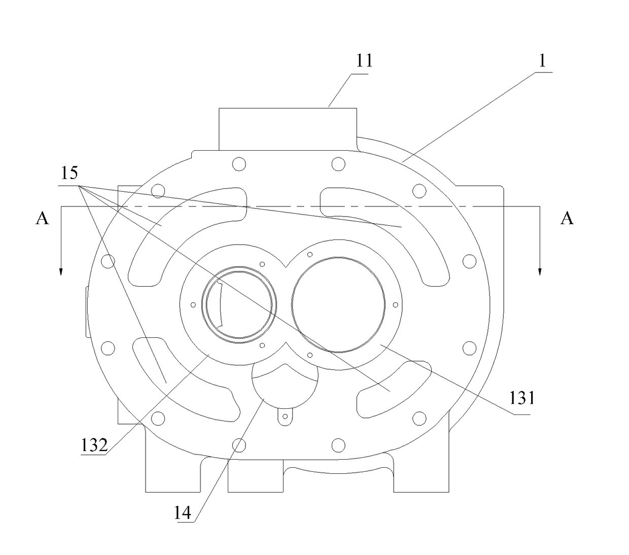
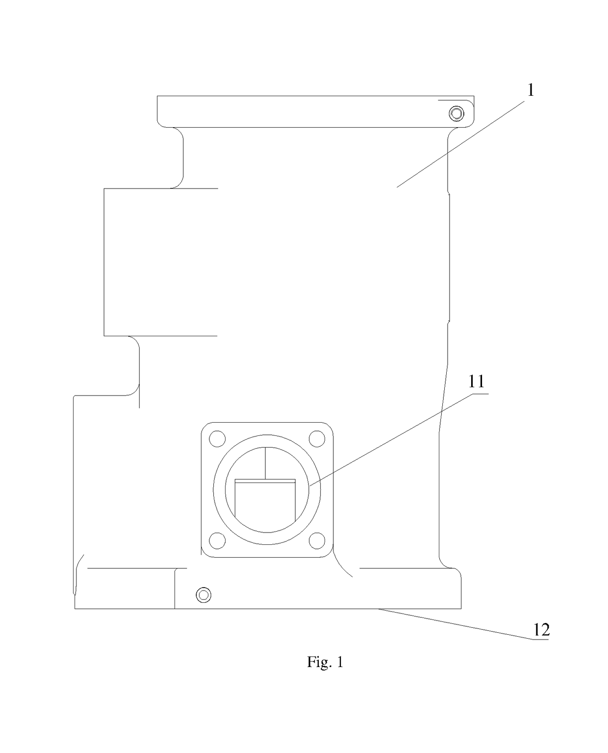
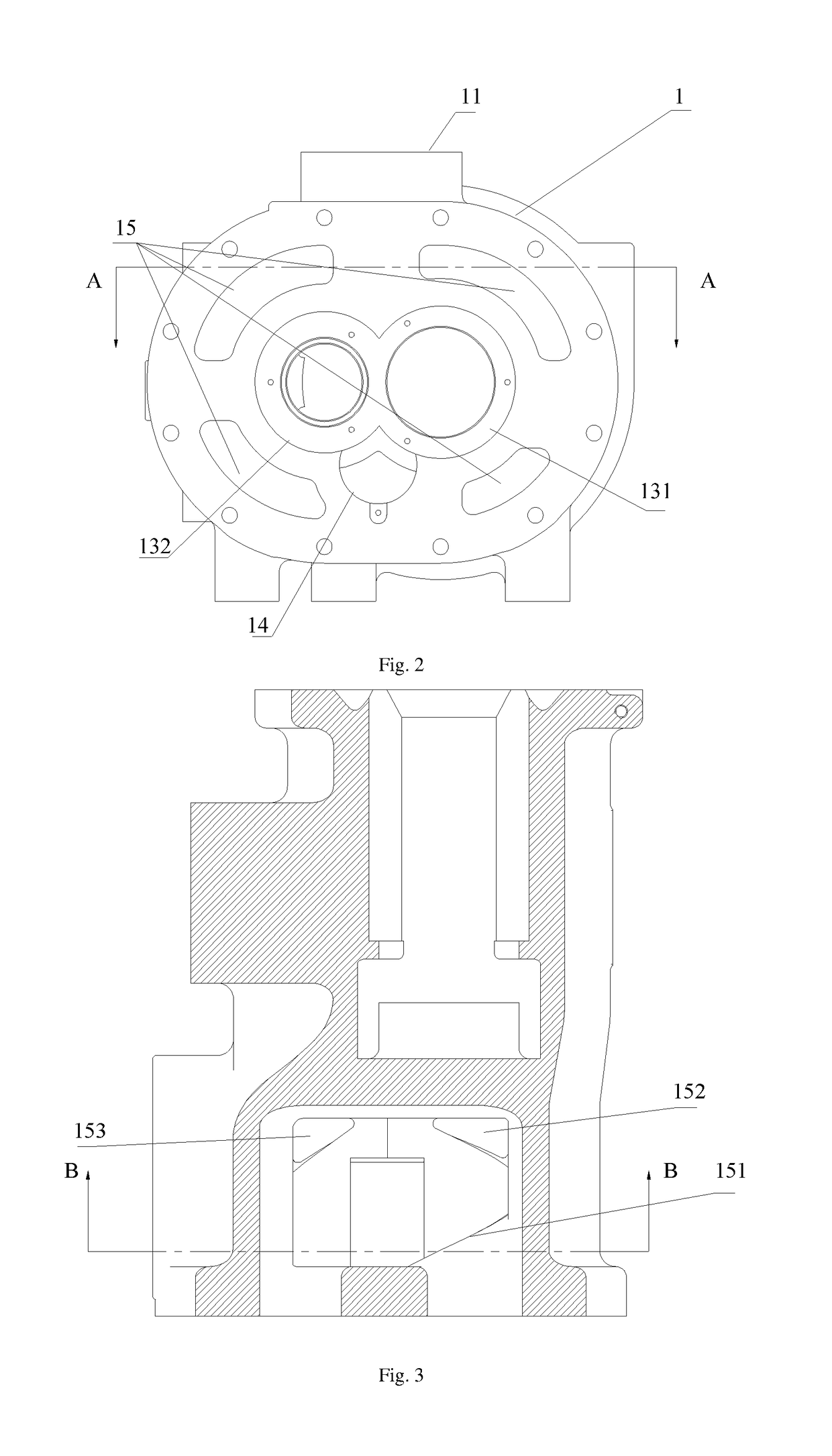
[0024]With reference to FIGS. 1-4, the compressor body comprises a housing 1 provided with an suction inlet 11 and an discharge end face 12, the housing 1 is internally provided with a rotor chamber and a spool chamber 14, the housing 1 is provided with a cooling chamber 15 around the rotor chamber, the cooling chamber 15 communicates with the suction inlet 11, and the cooling chamber 15 is provided wi...


PUM


Abstract

A screw compressor and a compressor body thereof, in which the compressor body includes a housing provided with a suction inlet and a discharge end face, the housing is internally provided with a rotor chamber and a spool chamber, the housing is provided with a cooling chamber around the rotor chamber, the cooling chamber communicates with the suction inlet, and the cooling chamber is provided with an air inlet communicating with the rotor chamber.

Description

RELATED APPLICATION[0001]The present application claims the priority right of the Chinese patent application No. 201510585999.5 filed as “A SCREW COMPRESSOR AND A COMPRESSOR BODY THEREOF” such that the full text thereof is cited here as reference.FIELD OF THE INVENTION[0002]The present application relates to the technical field of a compressor, and more particularly, relates to a screw compressor and a compressor body thereof.BACKGROUND OF THE INVENTION[0003]The screw compressor generally presents two air suction manners, in which the first is in a way such that the sucked air after cooling the motor enters the rotor chamber; and the second is in a way such that the sucked air directly entered the rotor chamber. Such two suction manners cannot sufficiently cool the rotor chamber. Due to the limit by the wall structure of the rotor chamber of the compressor, noise in the operation process of the compressor is easily radiated out.[0004]Accordingly, how to reduce noise of the compresso...

Claims


Application Information

Patent Timeline
Patent Type & Authority Applications(United States)
IPC IPC(8): F04C29/04F04C18/16F04C29/12F04C29/06
CPCF04C29/04F04C18/16F04C29/124F04C29/06F04C2240/30F04C2240/20F01C21/10F04C29/12
Inventor YANG, QIAOMINGLI, RIHUAZHANG, TIANYILIU, HUABI, YUSHIPENG, YANHAILIN, SHURUXU, KANGMA, BINMENG, QIANGJUNZHAO, ZHAORUICHEN, WENQINGXING, ZIWEN
Owner GREE ELECTRIC APPLIANCES INC
Why Eureka
Try Eureka