Method for Coating a Substrate and Metal Alloy Vacuum Deposition Facility

a vacuum deposition facility and substrate technology, applied in vacuum evaporation coating, chemical vapor deposition coating, coatings, etc., can solve the problems of difficult industrial implementation of this process, inconceivable, complicated and expensive subsequent diffusion heat treatment, etc., and achieve simple industrial implementation

Inactive Publication Date: 2018-04-26
ARCELORMITTAL INVESTIGACION Y DESARROLLO SL
View PDF0 Cites 1 Cited by
  • Summary
  • Abstract
  • Description
  • Claims
  • Application Information

AI Technical Summary

Benefits of technology

[0012]An object of the present invention is therefore to remedy the drawbacks of the processes and facilities of the prior art by providing a vacuum deposition facility for depositing coatings formed from metal alloys and a process for manufacturing a metal strip covered with a metal alloy layer, which allow simple industrial implementation, in few steps, but which also allow a coating of constant composition to be obtained, on various types of substrates.
[0029]means for adjusting the composition of the metal alloy bath, enabling it to be kept constant over the course of time.

Problems solved by technology

However, industrial implementation of this process is difficult and is not conceivable for production that must guarantee a stable coating composition over long substrate lengths.
However, the subsequent diffusion heat treatment may prove to be complicated and expensive as it involves the use of large quantities of inerting gas in order to prevent any oxidation of the coating at high temperature during the heat treatment.
This heat treatment may also pose problems in the case of certain materials that are not compatible with an excessively large temperature rise.
Moreover, in this type of process, it is very tricky to obtain a coating of constant composition over a long substrate length as it is necessary for the thicknesses of each layer to be very precisely controlled over the course of time.
Finally, the diffusion treatment does admittedly allow the alloy to form, but it may also lead to the diffusion of elements from the substrate to the coating, thus contaminating the interface with the substrate.

Method used


Image

  • Method for Coating a Substrate and Metal Alloy Vacuum Deposition Facility
  • Method for Coating a Substrate and Metal Alloy Vacuum Deposition Facility
  • Method for Coating a Substrate and Metal Alloy Vacuum Deposition Facility

Examples


first embodiment

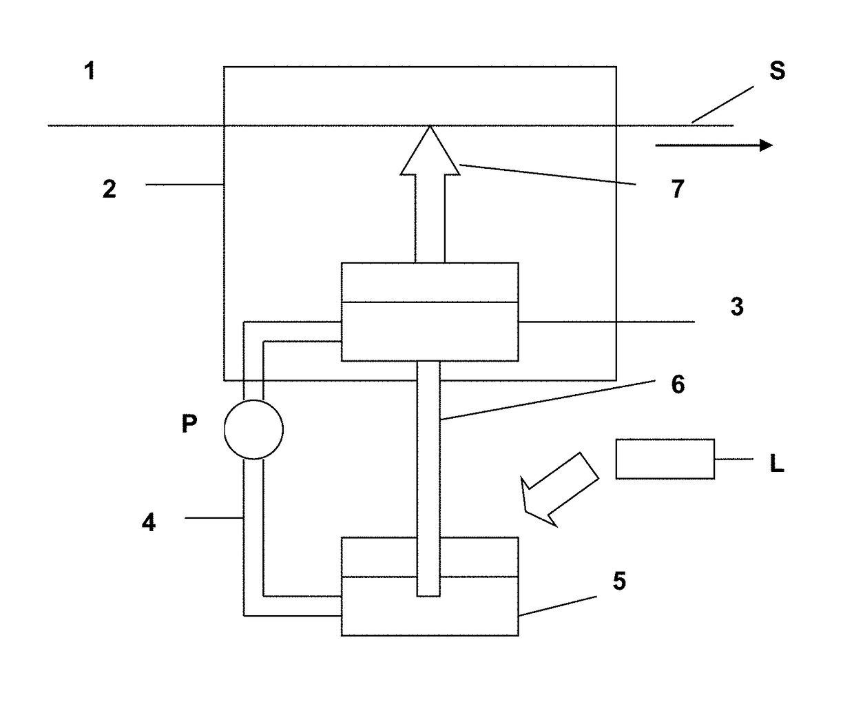
[0050]a facility according to the invention is shown more particularly in FIG. 2, which shows a facility 1 comprising a vacuum deposition chamber 2. This chamber 2 is preferably kept at a pressure of between 10−8 and 10−4 bar, for example. It has an entry load-lock and a exit load-lock between which a substrate S, such as for example a steel strip, runs.

[0051]The substrate S may be made to run by any suitable means, depending on the nature and the shape of said substrate. A rotary support roller on which a steel strip can bear may in particular be used.

[0052]Placed opposite the face of the substrate S which has to be coated there is a small extraction chamber 7 provided with a narrow slot, the length of which is close to the width of the substrate to be coated. This chamber may for example be made of graphite and may be mounted, directly or otherwise, on an evaporation crucible 3 that contains the liquid metal to be deposited on the substrate S. The evaporation crucible 3 is continu...

second embodiment

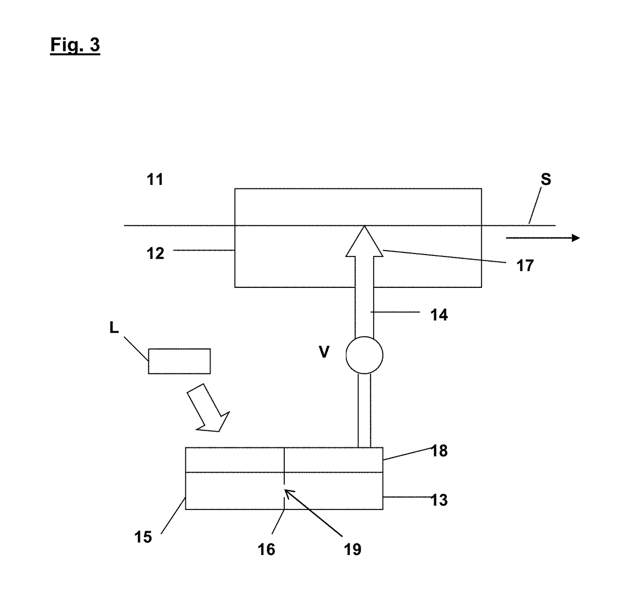
[0060]In a second embodiment as shown in FIG. 3, a facility 11 comprises a vacuum deposition chamber 12 similar to the chamber 2. An evaporation crucible 13 is placed under the vacuum chamber 12 and is connected via a pipe 14 thereto.

[0061]A recharging furnace 15 is placed alongside the evaporation crucible 13, the two components sharing a common wall 16 pierced by a communication opening 19 placed below the level of the metal alloy bath but above the bottom of these components so as to prevent any impurities that settle at the bottom of the recharging furnace 15 from being introduced into the evaporation crucible 13.

[0062]The evaporation crucible 13 is moreover placed in a confined chamber 18, placed outside the vacuum chamber 12.

[0063]The pipe 14 feeds a JVD coater 17, similar to the coater 7.

[0064]In the same way as described above with respect to FIG. 2, the composition of the coating which it is desired to obtain on the substrate is first determined and then deduced from this i...


PUM

PropertyMeasurementUnit
pressureaaaaaaaaaa
pressureaaaaaaaaaa
thicknessaaaaaaaaaa

Abstract

A vacuum deposition facility for continuously depositing coatings formed from metal alloys having at least two metallic elements on a running substrate is provided. The vacuum deposition facility includes a vacuum deposition chamber, a substrate running through the vacuum deposition chamber and an evaporation crucible inside the vacuum deposition chamber. The evaporation crucible includes a heater and a bath of molten metal alloy which has at least two metallic elements in a predetermined and constant ratio. The evaporation crucible evaporates the molten metal alloy into a vapor. The vacuum deposition facility also includes a coater inside the vacuum deposition chamber and connected to the evaporation crucible. The coater sprays a face of the running substrate with the vapor at a sonic velocity in order to deposit a coating on the running substrate. The vapor includes the at least two metallic elements in the predetermined and constant ratio.

Description

CROSS REFERENCE TO RELATED APPLICATIONS[0001]This is a continuation of U.S. application Ser. No. 13 / 870,351 filed on Apr. 25, 2013 which is a continuation of U.S. application Ser. No. 12 / 532,043 filed Dec. 31, 2009, now U.S. Pat. No. 8,481,120, the entire disclosures of which are hereby incorporated by reference herein.[0002]The present invention relates to a process for continuously coating a substrate and to a vacuum deposition facility for coatings formed from metal alloys, such as for example zinc-magnesium alloys, said process being more particularly suited for coating a steel strip, without in any way being limited thereto.BACKGROUND[0003]Various processes for depositing metal coatings composed of alloys on a substrate, such as a steel strip, are known. Among these, mention may be made of hot-dip coating, electrodeposition and also the various vacuum deposition processes, such as vacuum evaporation and magnetron sputtering.[0004]Thus, a vacuum evaporation process, described in...

Claims


Application Information

Patent Timeline
Patent Type & Authority Applications(United States)
IPC IPC(8): C23C16/06C23C14/56C23C14/16C23C14/24C23C16/455
CPCC23C16/45563C23C16/06C23C14/24C23C14/16C23C14/562C23C14/56
Inventor CHOQUET, PATRICKSILBERBERG, ERICSCHMITZ, BRUNOCHALEIX, DANIEL
Owner ARCELORMITTAL INVESTIGACION Y DESARROLLO SL
Why Eureka
Try Eureka