Eureka AIR delivers breakthrough ideas for toughest innovation challenges, trusted by R&D personnel around the world.

Dynamic inwardly eccentrically-placed directional drill bit type rotation guidance apparatus

a directional drill bit and eccentric positioning technology, applied in the direction of directional drilling, drilling machines and methods, borehole/well accessories, etc., can solve the problems of large lateral force and high deflection rate, drill bit and drill bit bearing wear more seriously, and large doglegs

Active Publication Date: 2018-04-12
SOUTHWEST PETROLEUM UNIV
View PDF0 Cites 2 Cited by
  • Summary
  • Abstract
  • Description
  • Claims
  • Application Information

AI Technical Summary

Benefits of technology

The present invention is a rotation guidance device for drilling oil wells that has several technical effects. Firstly, it allows for a smooth transition between straight drilling and stable inclination by controlling the rotation of the drill bit using the motion of the eccentrically-placed valve core. Secondly, it provides a new dynamic drill bit type that avoids the shortcomings of existing methods, such as the lack of rotation in a static eccentrically-placed push-the-bit drill bit type or the limited deflection capacity in a dynamic eccentrically-placed push-the-bit drill bit type. Lastly, it allows for full rotation of the drill bit, reducing friction force between the drill stem and the well wall, leading to a deeper horizontal well section.

Problems solved by technology

Moreover, the well depth limit may reach 15 km, and the drilling cost is low.
The push-the-bit rotation guidance system has large lateral force and high deflection rate, but holes drilled by rotation guidance have large doglegs and track fluctuation and are not smooth, and a drill bit and a drill bit bearing are worn more seriously.

Method used


Image

  • Dynamic inwardly eccentrically-placed directional drill bit type rotation guidance apparatus
  • Dynamic inwardly eccentrically-placed directional drill bit type rotation guidance apparatus
  • Dynamic inwardly eccentrically-placed directional drill bit type rotation guidance apparatus

Examples


Embodiment Construction

[0035]In addition to mutually exclusive features and / or steps, all the features or all the steps in methods or processes disclosed in the description may be combined in any forms.

[0036]Any feature disclosed in the description (including any attached claims and abstract) may be, unless specially described, replaced by other equivalent or substitutive features having similar purpose. That is, unless specially described, each feature is merely an example among a series of equivalent or similar features.

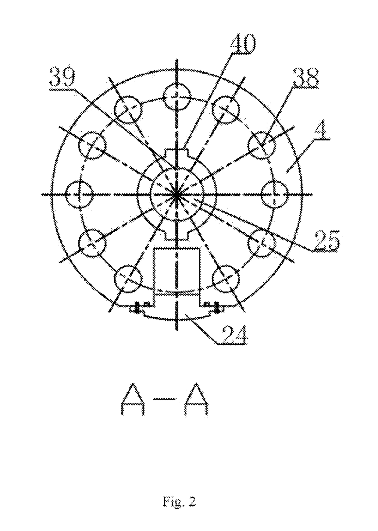
[0037]As shown in FIG. 1 and FIG. 2, the rotation guidance apparatus of the present invention comprises an upper connector 4, a lower connector 3 and a ball-joint rod 12. The upper connector 4 is connected to the lower connector 3 through threads; a central through hole is provided in the center of each of the lower connector 3 and the ball-joint rod 12. More than three through piston holes that are located in the same circumference are evenly distributed in a side wall of the lower conn...


PUM


Abstract

Disclosed is a rotation guidance apparatus belonging to the technical field of oil drilling equipment. An end part of a lower connector (3) has a ball-socketed ball-joint rod (12), and a drill bit (1) is connected to the ball-socketed ball-joint rod (12); several circumferentially and evenly distributed piston holes are provided in a side wall of the lower connector (3), a piston matches each piston hole, and a piston rod (11) connected to the piston is movably connected to the ball-socketed ball-joint rod (12); and a eccentrically-placed valve core (17) is connected to a controller provided in an upper connector (4), a working face of the eccentrically-placed valve core (17) is opposite to the piston holes, and rotation of the eccentrically-placed valve core (17) makes the pistons in the piston holes move to control the rotation guidance of the ball-socketed ball-joint rod (12).

Description

CROSS REFERENCE TO RELATED APPLICATIONS[0001]This application is the national phase entry of International Application No. PCT / CN2015 / 082089, filed on Jun. 23, 2015, which is based upon and claims priority to Chinese Patent Application No. CN201410361802.5 filed on Jul. 28, 2014, the entire contents of which are incorporated herein by reference.TECHNICAL FIELD[0002]The present invention relates to the field of oil drilling equipment, in particular to a closed-loop rotation guidance drilling technology.BACKGROUND ART[0003]In recent ten years, with rapid development of a horizontal well, an extended-reach well, a multilateral well and other complex structural wells as well as “offshore oil production on land” and shale gas development, and upon the requirements of a drilling technology to reduce the efficiency, reducing the cost, improving the drilling capacity, etc., under severe environments and complicated geological conditions, the research about the rotation guidance drilling tec...

Claims


Application Information

Patent Timeline
Patent Type & Authority Applications(United States)
IPC IPC(8): E21B7/06
CPCE21B7/064E21B7/068E21B34/06E21B7/04E21B34/066E21B7/06
Inventor LI, WEILEI, HONGXIANGLIU, QINGYOUXIAO, SHIHONGSI, XUZHANG, TIESHANTU, QINGTAN, XIAOJIN, FANYAOWANG, XINGMINGZHONG, YUANLI, HANGWU, JIANCHUANLI, DENGWEI
Owner SOUTHWEST PETROLEUM UNIV
Why Eureka
Eureka Blog
Learn More