
Aircraft having independently variable incidence channel wings with independently variable incidence channel canards

a technology of incidence channel and incidence channel, which is applied in the direction of canard-type aircraft, vertical landing/take-off aircraft, efficient propulsion technologies, etc., can solve the problems of conventional aircraft control surface wings that cannot can not vertically take off and land vertically, etc., and achieve great maneuverability in hover

Active Publication Date: 2018-03-29
HOP FLYT INC
View PDF7 Cites 29 Cited by
  • Summary
  • Abstract
  • Description
  • Claims
  • Application Information

AI Technical Summary

Benefits of technology

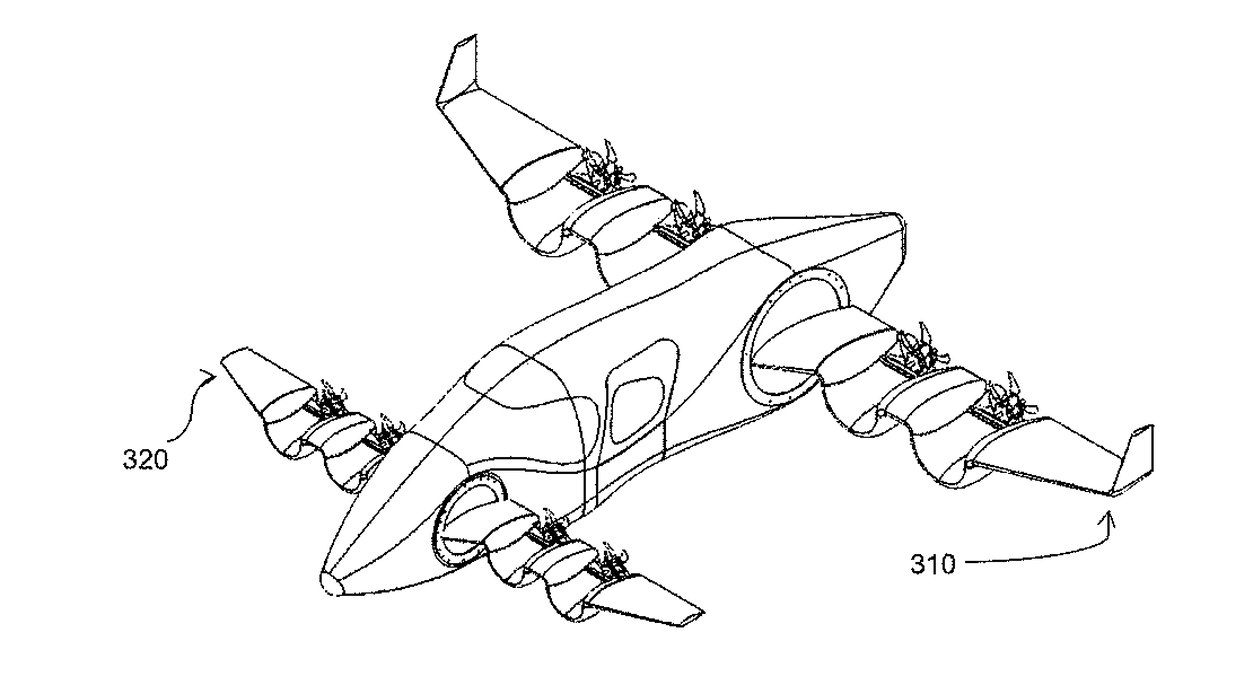
The present invention describes an aircraft that combines a channel wing with an independently variable incidence wing and a channel canard with an independently variable incidence canard. This arrangement allows for vertical takeoff and landings, high payload capacity, and high cruise speeds. The aircraft does not require conventional control surfaces because controllability will be achieved by varying incidence and the lift in the wing and canard channels. The angle of incidence of a wing and the canard can be varied to provide the required lift for takeoff and landing. The wings and canards rotate to a cruise position for forward flight, maintaining a level position relative to the horizon. The aircraft is also highly maneuverable in hover and can fly in reverse flight.

Problems solved by technology

However, a fixed incident channel wing with conventional aircraft control surfaces is unable to takeoff and land vertically because of lack of controllability at very low airspeeds.
Variable incidence wings have been used to lower takeoff arid landing speeds and thus reduce the distances to take off and land but are unable to vertically take off and land because of lack of lift.

Method used


Image

  • Aircraft having independently variable incidence channel wings with independently variable incidence channel canards
  • Aircraft having independently variable incidence channel wings with independently variable incidence channel canards
  • Aircraft having independently variable incidence channel wings with independently variable incidence channel canards

Examples


Embodiment Construction

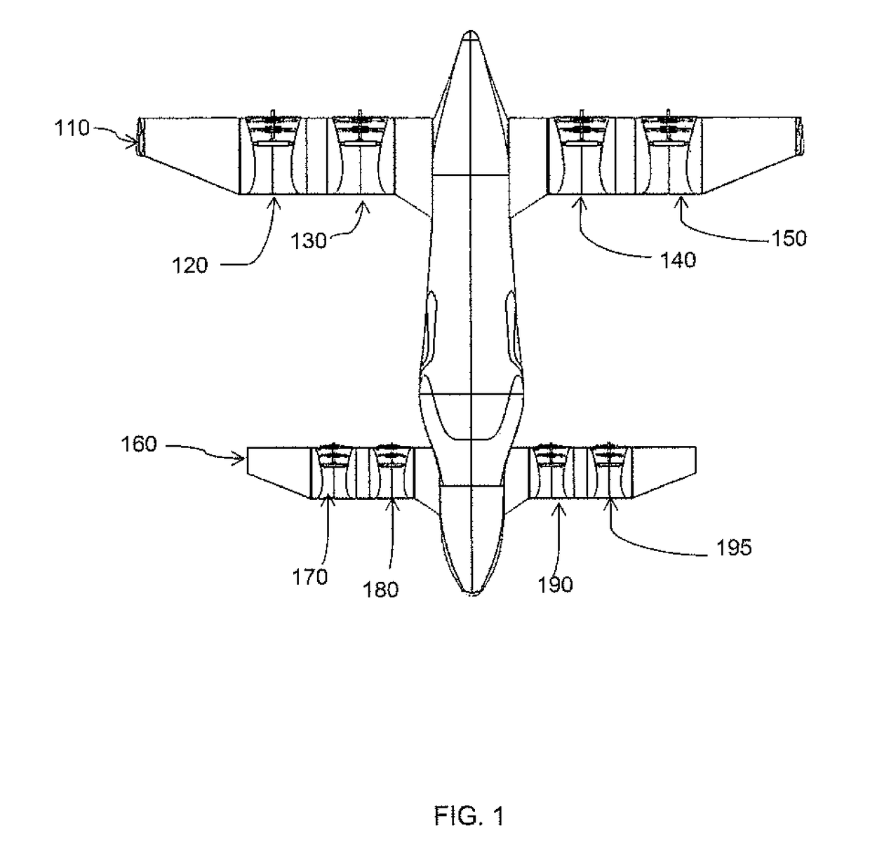
[0015]FIG. 1 is a diagram illustrating the aircraft at rest. In this diagram the aircraft's wing 110 is made up of four channels 120, 130, 140 and 150. The aircraft's canard 160 is made of four channels 170, 180, 190 and 195.

[0016]FIG. 2 is a diagram illustrating the aircraft in the vertical takeoff and landing configuration of the present invention. The aircraft of the present invention will be able to independently vary the incidence of the wing 210 as well as the angle of incidence of the canard 220 as required for takeoff, landing, and flight. During liftoff the channel wings and channel canards rotate such that the resultant of the thrust from the propellers and the lift from the wings and canards provide the lift required for vertical takeoff. A portion of the channel wing 230 and the channel canard 240 can become a ducted propeller, by enclosing the propeller(s) with a retractable mechanism, for takeoff and landing allowing for extra thrust, reduction of noise and protection ...


PUM


Abstract

An aircraft includes a fuselage and a pair of channel wings which may vary incidence with respect to the fuselage and a pair of channel canards which can also vary incidence with respect to the fuselage and that can move independently of each other for the purpose of vertical takeoff and landing as well as forward and reverse flight. The wings may have multiple channels and may be powered by single propeller or contra-rotating propellers. The thrust to the propellers may be provided with an internal combustion engine or electric motors or a turbo prop or hybrid system. The channel wing allows the fuselage to maintain a level pitch with respect to the horizon. The aircraft will also have increased maneuverability in hover because it can independently vary the incidence of the wings and canards and be able to tightly turn about a point.

Description

CROSS REFERENCE TO RELATED APPLICATION[0001]This application claims the benefit of U.S. Provisional Patent Application No. 62 / 384,740 filed Sep. 8, 2016.BACKGROUND OF THE INVENTION[0002]The present invention relates to aircraft and a wing or a portion of a wing that is comprised of an airfoil which transcribes an arc to channel air accelerated by a propeller the purpose of providing lift, herein called a channel wing. In particular, the present invention is directed toward an aircraft having a fuselage and channel wings and channel canards that may vary incidence independent of each other and with respect to the fuselage for the purpose of vertical takeoff and landing, forward flight, reverse flight, hovering and hovering turns.[0003]Aircraft that can vertically takeoff and land, have a high payload capacity and a high forward speed are desirable. A channel wing is a method to provide additional lift and has been used for short takeoff and landing aircraft. However, a fixed incident...

Claims


Application Information

Patent Timeline
IPC IPC(8): B64C29/00B64C3/38
CPCB64C29/0033B64C3/385B64D2027/026B64D27/12B64D27/24B64C3/32B64C39/12Y02T50/60B64D27/026B64C39/066
Inventor WINSTON, ROBERT ALLEN
Owner HOP FLYT INC
Learn More