
Method and System for Transmitting Control Commands for Units in a Distributed Arrangement

a technology of control commands and distributed arrangement, which is applied in the direction of digital transmission, transmission, data switching networks, etc., can solve the problems of difficult to achieve temporal synchronization performance of lamps, and achieve the effect of preventing the cascading activation of lamps and accelerating the propagation significantly faster

Active Publication Date: 2018-03-22
ZUMTOBEL LIGHTING GMBH & CO KG
View PDF5 Cites 0 Cited by
  • Summary
  • Abstract
  • Description
  • Claims
  • Application Information

AI Technical Summary

Benefits of technology

The invention is a method of transmitting data between devices by adding temporal data to the command and calculating waiting times based on this data. The method is designed to make the transmission and calculation of times easier and faster, and to store data regarding the global transmission period with minimal effort. This approach helps to achieve low losses in synchronized performance among devices and offers clear advantages over existing methods.

Problems solved by technology

One of the problems known with such systems is that, with regard to the light output, it is relatively simple to obtain a coordinated performance of the lamps, whereas a temporally synchronized performance of the lamps is much more difficult to achieve.
The problems described above also exist independently of whether the control commands are transmitted via a signal line or in a wireless manner, e.g. by radio or infrared radiation, because in both cases, the control command must be resent, in particular with large systems, in order to be able to propagate over the entire system.
These problems are also not specific to lighting systems, but instead, also pertain to other systems that have loads in a distributed arrangement, with which it is desired that the loads react substantially simultaneously to a control command.

Method used


Image

  • Method and System for Transmitting Control Commands for Units in a Distributed Arrangement
  • Method and System for Transmitting Control Commands for Units in a Distributed Arrangement
  • Method and System for Transmitting Control Commands for Units in a Distributed Arrangement

Examples


Embodiment Construction

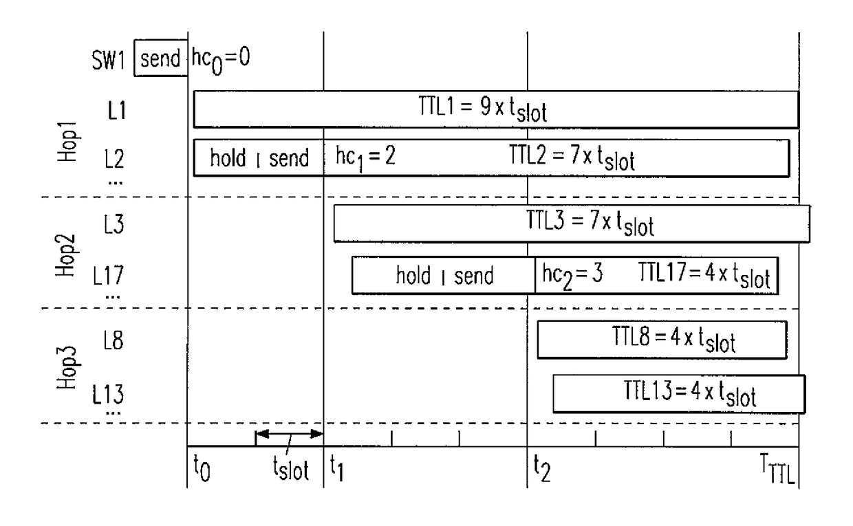
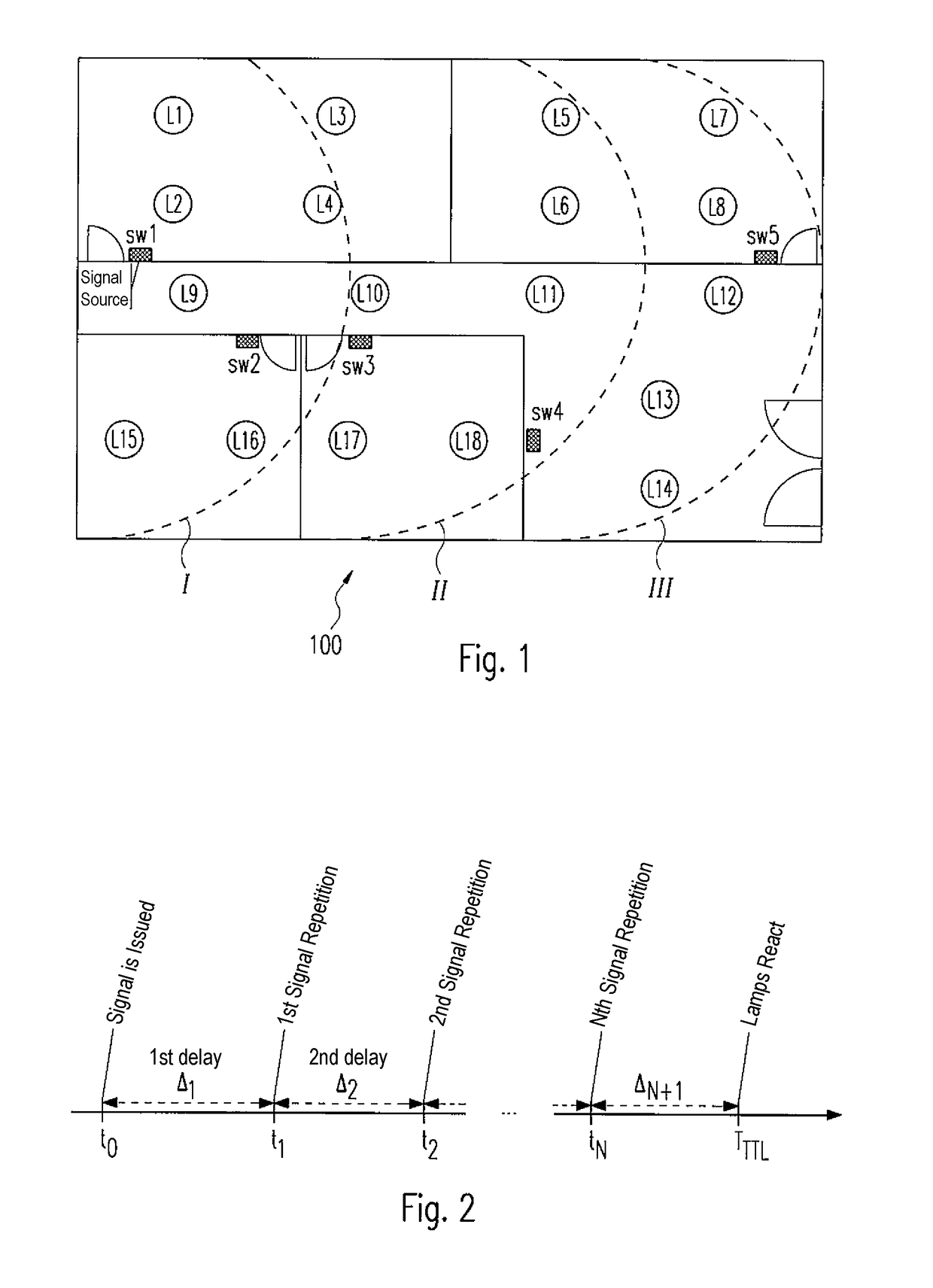
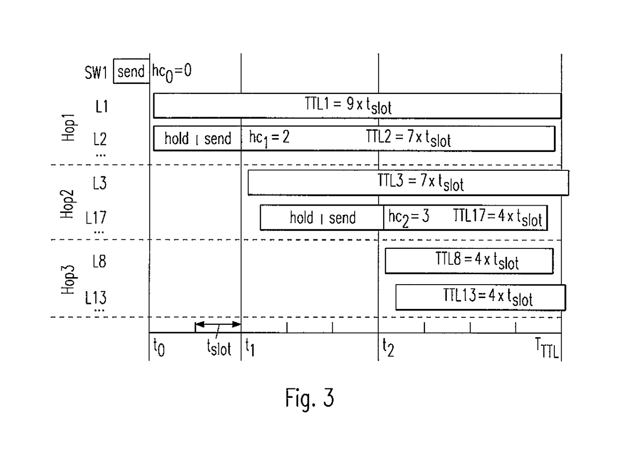
[0023]The invention shall be explained in greater detail below based on a lighting system in which the control commands are transmitted wirelessly—e.g. by radio or infrared—to lamps of the system in a distributed arrangement. As specified above, however, the present invention is not limited to lighting systems, even though temporal deviations in the activation of the units of the system can be most easily observed here. It may also be the case that a synchronized performance of the various units in other systems is desired, e.g. in a system for central activation of shading systems such as blinds or the like, for which reason, the invention can be used in a very versatile manner.

[0024]Furthermore, the approach according to the invention can be applied in a simple manner to systems in which the signal transmission is not wireless, but instead takes place via physical lines. This may be the case, in particular, when there are complex bus systems, in which numerous different subsystems...


PUM


Abstract

A method for transmitting control commands in a system (100) of units (L1-L18) in a distributed arrangement, for example in a lighting system having luminaires in a distributed arrangement, involves at least some of the units (L1-L18) sending a received control command again in order to ensure that the control command is forwarded to all units (L1-L18). The control command contains a piece of information regarding an already past command transmission time, wherein each unit (L1-L18) takes the command transmission time that a received command contains as a basis for determining an individual waiting time (TTLind), after the expiry of which the command is executed by the unit (L1-L18).

Description

[0001]The present application is the U.S. national stage application of International Application PCT / EP2016 / 059492, filed Apr. 28, 2016, which international application was published on Nov. 3, 2016 as International Publication WO 2016 / 174139 A1. The International Application claims priority to German Patent Application 10 2015 207 985.6 filed Apr. 30, 2015.FIELD OF THE INVENTION[0002]The present invention relates to a method for transmitting control commands in a system of units in a distributed arrangement, e.g. in a lighting system having lamps in a distributed arrangement. Furthermore, the invention relates to a corresponding system having units in a distributed arrangement, wherein, through the use of the invention, a temporally synchronized performance of all of the units is sought when executing control commands.BACKGROUND OF THE INVENTION[0003]Larger lighting systems, in which numerous lamps are activated by a central control device, have the advantage, in comparison with l...

Claims


Application Information

Patent Timeline
Patent Type & Authority Applications(United States)
IPC IPC(8): H04L12/721H05B37/02
CPCH04L45/44H05B37/0272H05B37/0218H05B47/16H05B47/155Y02B20/40H05B47/195H05B47/19H05B47/11
Inventor ZEIDLER, GERDLOURENCO, NUNO
Owner ZUMTOBEL LIGHTING GMBH & CO KG
Learn More