Actuator Assembly for Locking Devices

a technology of locking device and actuator, which is applied in the direction of building locks, wing knobs, constructions, etc., can solve the problems of failure to allow pins to enter the spiral track, wear-out of pins and springs, etc., to reduce friction between pins and springs, reduce wear-out and damage of components, and simple structure

Inactive Publication Date: 2018-03-22
SHENZHEN SUOZHIDAO TECH +1
View PDF3 Cites 1 Cited by
  • Summary
  • Abstract
  • Description
  • Claims
  • Application Information

AI Technical Summary

Benefits of technology

[0021]1. Compared with the prior art, the follower shaft of the present invention effectively maintains a radial limitation of the cylinder spring to overcome the vibration of the spring occurred during the rotation of the cylinder spring and the axial displacement of the follower shaft.
[0022]2. The cylinder spring of the present invention has the structure of the buffering portion, and when the pin displaces axially with respect to the cylinder spring, the buffering portion is also pulled and stretched, so that the rotating-in portion of the spring is pulled and stretched and the compression is reduced to effectively reduce the friction between the pin and the spring, so as to minimize the wear-out and damage of components.
[0023]3. The actuator assembly for the locking device in accordance with the present invention has the features of small number of components, simple structure, and easy manufacture and installation.

Problems solved by technology

As to the solution of using the rotation of the pin, when the pin moves spirally along the spring, the spring is compressed by the pressure of the pin, so that a larger friction is produced, and a rotational force of the spring and the shaft is produced by the friction, so that the spring may be rotated together with the shaft and jittered radially, and the spring cannot be displaced stably in the axial direction, and thus not just resulting the wear-out or damage between the spring and the sliding block only, but also failing to allow the pin to enter into the spiral track of the spring successfully.
In addition, the friction between the pin and the spring may also wear out the pin and the spring.
However, there is still an unsatisfactory result.
For example, the load (including the bushing of the plug and the locking plate) has relatively larger volume and weight, so that when the spring is rotated into the pin, the spring is pulled and stretched, and the friction in contact with the pin is increased, and the spring and pin may be worn out or damaged easily.
In addition, some actuator assemblies require a spring with a fixed end and a non-fixed longer end, so that when a portion of the actuator assembly away from the drive shaft is rotated, there is no radial limitation, and a swinging deviated from the axis may be produced to cause vibrations of the spring.

Method used


Image

  • Actuator Assembly for Locking Devices
  • Actuator Assembly for Locking Devices
  • Actuator Assembly for Locking Devices

Examples


Embodiment Construction

[0032]The above and other objects, features and advantages of this disclosure will become apparent from the following detailed description taken with the accompanying drawings.

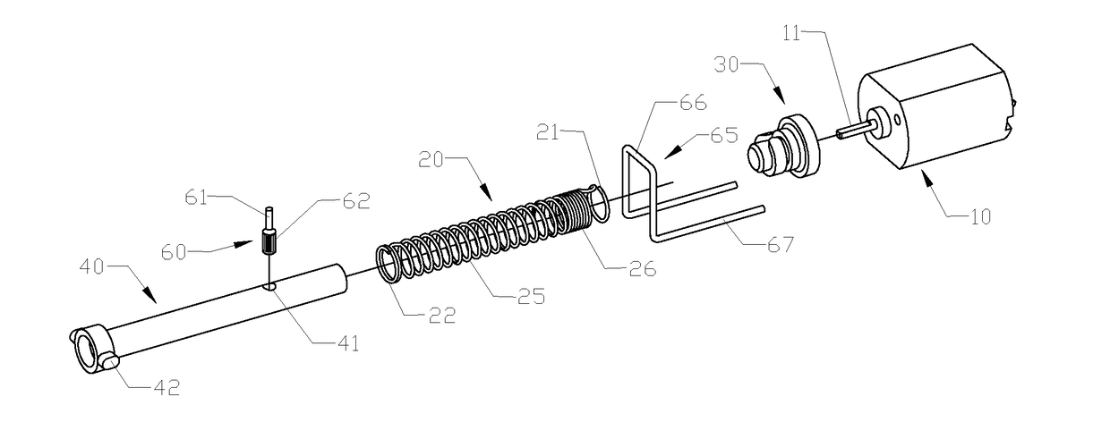
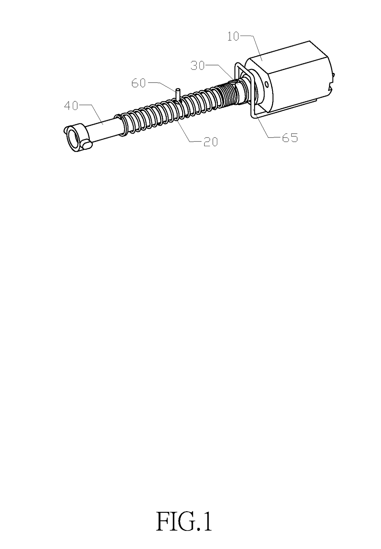
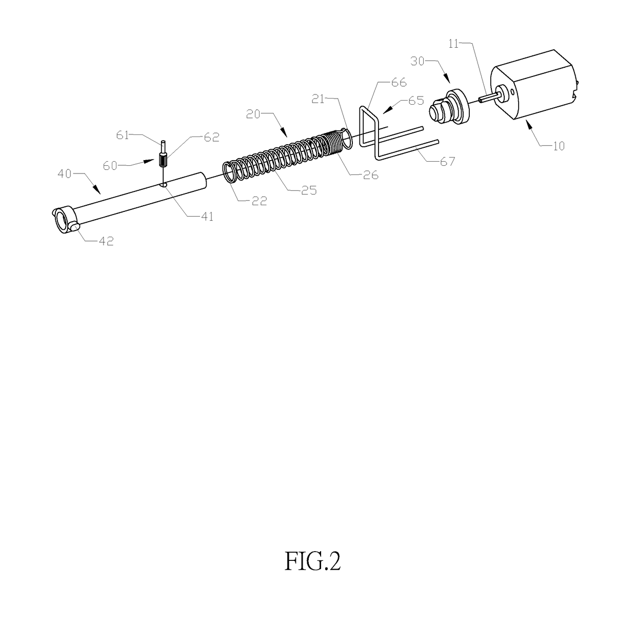
[0033]With reference to FIGS. 1 and 2 for an actuator assembly in accordance with a preferred embodiment of the present invention, the actuator assembly comprises a motor 10, a drive shaft 30, a cylinder spring 20, a follower shaft 40, and a pin 60. The motor 10 is a general DC motor, and the drive shaft 30 and the motor shaft 11 are flat shafts in coordination with the torque of transmission, and the motor shaft 11 and the shaft hole 35 of the drive shaft are interference fitted and fixed. The two free ends of the cylinder spring 20 are configured in 1˜2 rounds of first fixing ring 21 and second fixing ring 22, and the first fixing ring 21 and the second fixing ring 22 are a first U-shaped bend 23 and a second U-shaped bend 24 coupled to each other in opposite directions and having the same shape, and the dri...


PUM


Abstract

This invention relates to locking devices and particularly to an actuator assembly for a locking device with electronic control. The actuator assembly includes: a motor, having a drive shaft installed to a motor shaft, and a coil spring installed to the drive shaft, and further includes: a follower shaft capable of displacing in an axial direction in the coil spring, and a pin installed onto the follower shaft and rotatable into the coil spring, and the follower shaft is extended into the coil spring and slidably fitted to the coil spring. Compared with the prior art, this invention effectively maintains a radial limitation of the cylinder spring to overcome the vibration of the spring occurred during the rotation of the cylinder spring and the axial displacement of the follower shaft.

Description

FIELD OF INVENTION[0001]The present invention relates to locking devices, in particular to an actuator assembly for a locking device with electronic control.BACKGROUND OF INVENTION1. Description of the Related Art[0002]Conventional locking device with an electronic control generally adopts a locking assembly driven by a micro DC motor, and one of the technical solutions uses a coil spring sheathed on a shaft and a pin fixed to the shaft to convert a rotational motion of the motor into a linear motion between the spring and the pin, so as to push or pull a blocking element for controlling a lock bolt to retract.[0003]As to the solution of using the rotation of the pin, when the pin moves spirally along the spring, the spring is compressed by the pressure of the pin, so that a larger friction is produced, and a rotational force of the spring and the shaft is produced by the friction, so that the spring may be rotated together with the shaft and jittered radially, and the spring cannot...

Claims


Application Information

Patent Timeline
Patent Type & Authority Applications(United States)
IPC IPC(8): E05B47/00
CPCE05B47/0012E05B2047/0037E05B15/04E05B47/0004E05B1/0038E05B47/0657E05B65/52E05B2015/0406E05B2047/0031E05B2047/0067
Inventor YUAN, MENGXIAO
Owner SHENZHEN SUOZHIDAO TECH
Why Eureka
Try Eureka