Roundness measuring machine

Active Publication Date: 2018-03-15
MITUTOYO CORP
View PDF7 Cites 6 Cited by
  • Summary
  • Abstract
  • Description
  • Claims
  • Application Information

AI Technical Summary

Benefits of technology

The invention is a roundness measuring machine that is improved in measuring efficiency and accuracy. It allows for the acceleration time or deceleration time to be set based on the workpiece's inertia moment. By doing so, the machine can be faster and more efficient in measuring roundness of multiple workpieces. Additionally, the machine can update the acceleration time and deceleration time as the starting current decreases, which improves accuracy.

Problems solved by technology

However, when the acceleration time is extremely short, the workpiece is unlikely to be appropriately measured at the desired rotation speed due to an insufficient acceleration of the workpiece.
However, a powerful driving mechanism is unsuitable for enhancing the accuracy because such a mechanism should be unnecessary excess equipment for a measurement state with a constant rotation speed and may mechanistically impose an excessive load on the measuring device as a whole.
Further, although an acceleration time shortened as much as possible is also favorable for an arrangement for controlling the acceleration of the table, an acceleration time suitable for the inertia moment of the workpiece mounted on the table is not automatically determinable.
If the determined acceleration time is shorter than an acceleration time suitable for the inertia moment of the workpiece, the table, which is affected by a large inertia moment, is controlled to be rapidly accelerated, causing a problem to the operation of a motor that drives the table.
Further, similar problems may be caused in relation to a time (deceleration time) elapsed before the workpiece is decelerated to the resting state after a brake is applied to the table with the workpiece being rotated.
In other words, when a brake is applied to a workpiece having a large inertia moment in a short time, a load on a mechanistical portion is disadvantageously increased.
Additionally, an angular position of the table is inaccurately determined when a brake is applied to a workpiece having a large inertia moment in a short time.
However, such a sufficiently long acceleration / deceleration time is longer than actually required acceleration / deceleration times for almost all the various workpieces.
This results in increasing the total time required to measure the workpieces and, consequently, in lowering a processing efficiency of the roundness measuring machine per unit time.

Method used


Image

  • Roundness measuring machine
  • Roundness measuring machine
  • Roundness measuring machine

Examples


Embodiment Construction

)

Roundness Measuring Machine

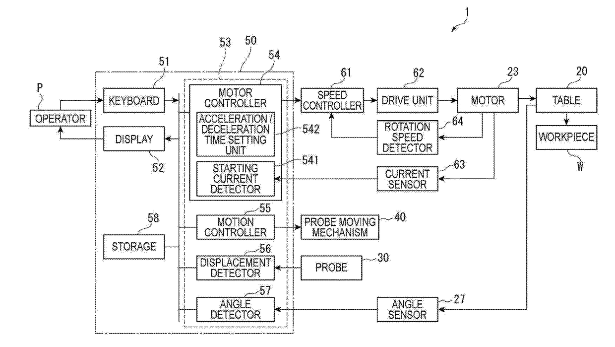
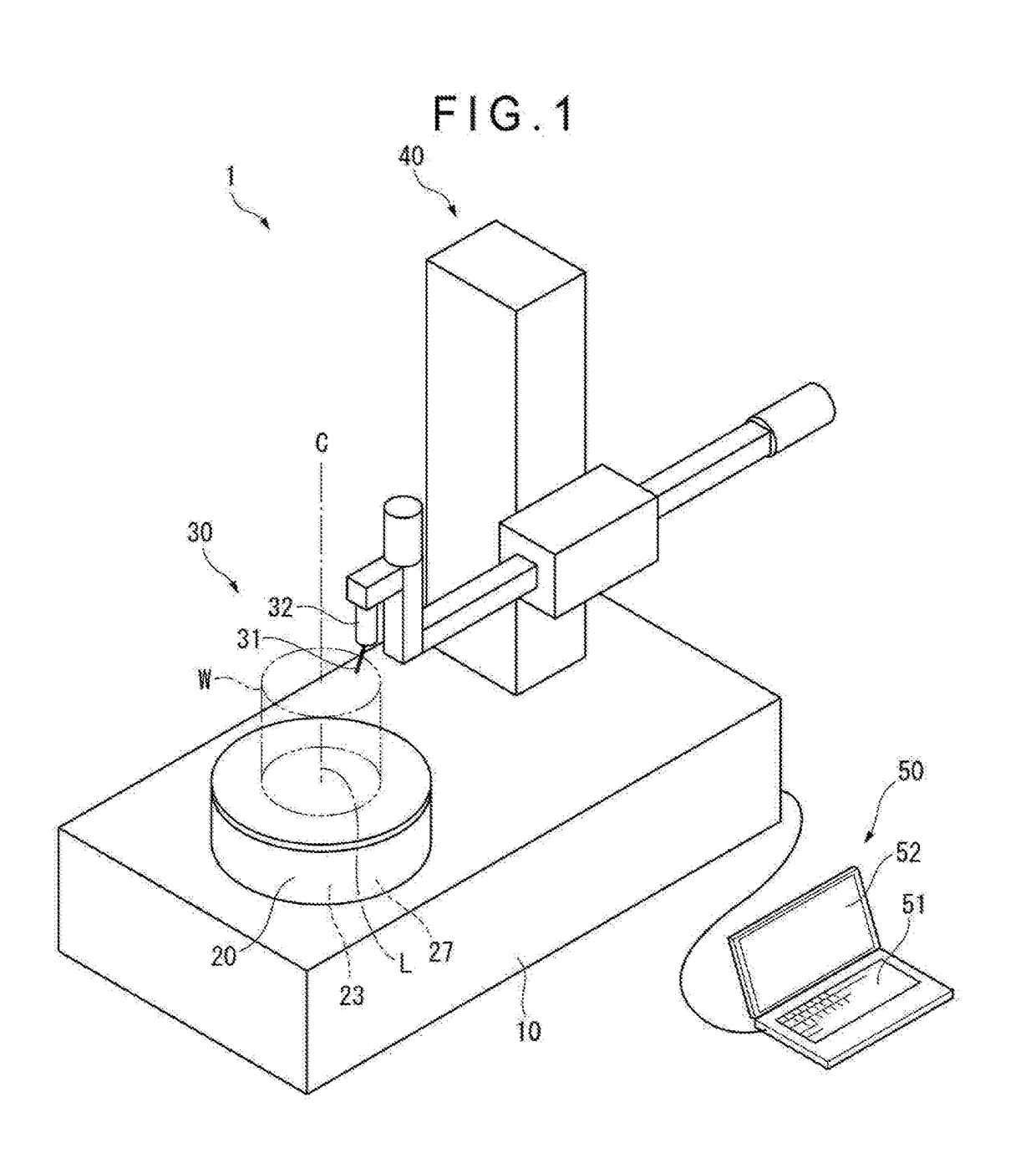
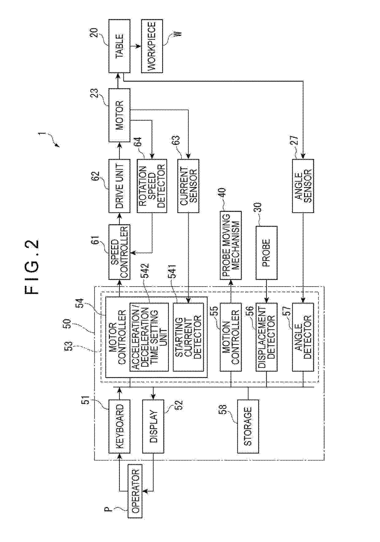
[0037]As shown in FIG. 1, a roundness measuring machine 1 includes a base 10, a table 20 rotatable relative to the base 10, a probe 30 that scans a surface of a workpiece W mounted on the table 20, a probe moving mechanism 40 that moves the probe 30, and a control device 50 that controls an operation of the probe moving mechanism 40 and performs a process on a scanning output from the probe 30.

[0038]The base 10 is installed with a motor 23 that rotates the table 20. The control device 50 controls an operation of the motor 23.

[0039]The table 20 is rotatable relative to the base 10 around a rotation axis L defined in a vertical direction. A workpiece W is to be mounted on an upper surface of the table 20. A center axis C of the workpiece W is aligned with the rotation axis L of the table 20.

[0040]The motor 23 rotates the table 20 via a decelerator or the like. The table 20 is rotated at a constant speed during the rotation of the motor 23 at a predetermined...


PUM


Abstract

A roundness measuring machine includes: a base; a table rotatable relative to the base; a probe configured to scan a surface of a workpiece mounted on the table; a motor configured to rotate the table; and a control device configured to control a rotation of the motor. The control device includes: a starting current detector configured to detect a starting current of the motor; and an acceleration / deceleration time setting unit configured to detect at least one of acceleration time and deceleration time for the motor in accordance with the starting current. The roundness measuring machine can suitably set the acceleration time and the deceleration time for the motor corresponding to the inertia moment of the workpiece mounted on the table.

Description

[0001]The entire disclosure of Japanese Patent Application No. 2016-178459 filed Sep. 13, 2016 is expressly incorporated by reference herein.TECHNICAL FIELD[0002]The present invention relates to a roundness measuring machine configured to measure a contour of a workpiece.BACKGROUND ART[0003]Roundness measuring machines are used to measure a contour of a workpiece.[0004]To measure a contour of a workpiece by a roundness measuring machine, the workpiece is mounted on a rotary table and a probe is brought into contact with a circumferential surface of the workpiece rotated along with the table (see Patent Literature 1: JP 2016-065751 A).[0005]To perform an accurate measurement, the roundness measuring machine may perform an operation control so that the rotation speed of the workpiece and the table falls within a predetermined range, when the probe is brought into contact with the circumferential surface of the workpiece to perform measurement.[0006]In measuring the circumferential sur...

Claims


Application Information

Patent Timeline
IPC IPC(8): G01B5/20
CPCG01B5/201G01B7/282G01B21/20
Inventor NAKAYAMA, TATSUKIOMORI, YOSHIYUKI
Owner MITUTOYO CORP
Why Eureka
Try Eureka