
Elastomeric element retention

Active Publication Date: 2018-03-15
TRANS TECH OF SOUTH CAROLINA INC
View PDF1 Cites 1 Cited by
  • Summary
  • Abstract
  • Description
  • Claims
  • Application Information

AI Technical Summary

Benefits of technology

This patent describes a mounting system for a current collection device on a rail vehicle. The system includes an elastomeric element and a retention system using locking and locating features. The elastomeric element is securely positioned and retained using a positive lock that cannot be overcome by the force of the element. The locking feature helps eliminate undesired motion of the element, which could result in premature failure. In one embodiment, the elastomeric element is fitted with metallic inner and outer rings to provide secure position retention. The outer ring is segmented to compress the elastomer and enhance its service life. The mounting assembly also includes a housing and an intermediate ring of elastomeric material between the inner hub member and the outer ring. The outer ring has multiple segments connected to the intermediate ring. The housing and the outer ring each have at least one locking feature that engages to prevent rotation of the elastomeric element. This mounting system securely holds the current collection device in place and prevents unwanted movements.

Problems solved by technology

This undesired motion can lead to improper positioning of the element, potentially resulting in premature failure of the elastomeric element.
In any case, the retention mechanism ideally should be configured such that it is not possible for any force transferred through the elastomeric to cause the position of the elastomeric element to not be retained.

Method used


Image

  • Elastomeric element retention
  • Elastomeric element retention
  • Elastomeric element retention

Examples


Embodiment Construction

[0033]For purposes of the description hereinafter, the terms “end”, “upper”, “lower”, “right”, “left”, “vertical”, “horizontal”, “top”, “bottom”, “lateral”, “longitudinal”, and derivatives thereof shall relate to the invention as it is oriented in the drawing figures. However, it is to be understood that the invention may assume various alternative variations and step sequences, except where expressly specified to the contrary. It is also to be understood that the specific devices and processes illustrated in the attached drawings, and described in the following specification, are simply exemplary embodiments or aspects of the invention. Hence, specific dimensions and other physical characteristics related to the embodiments or aspects disclosed herein are not to be considered as limiting.

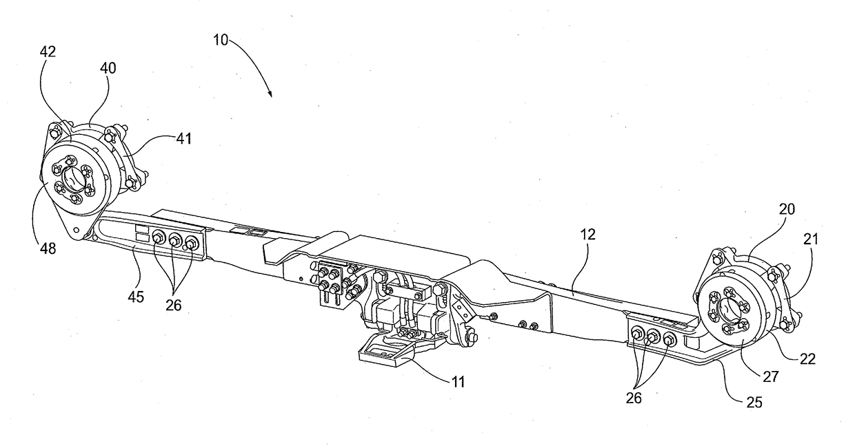
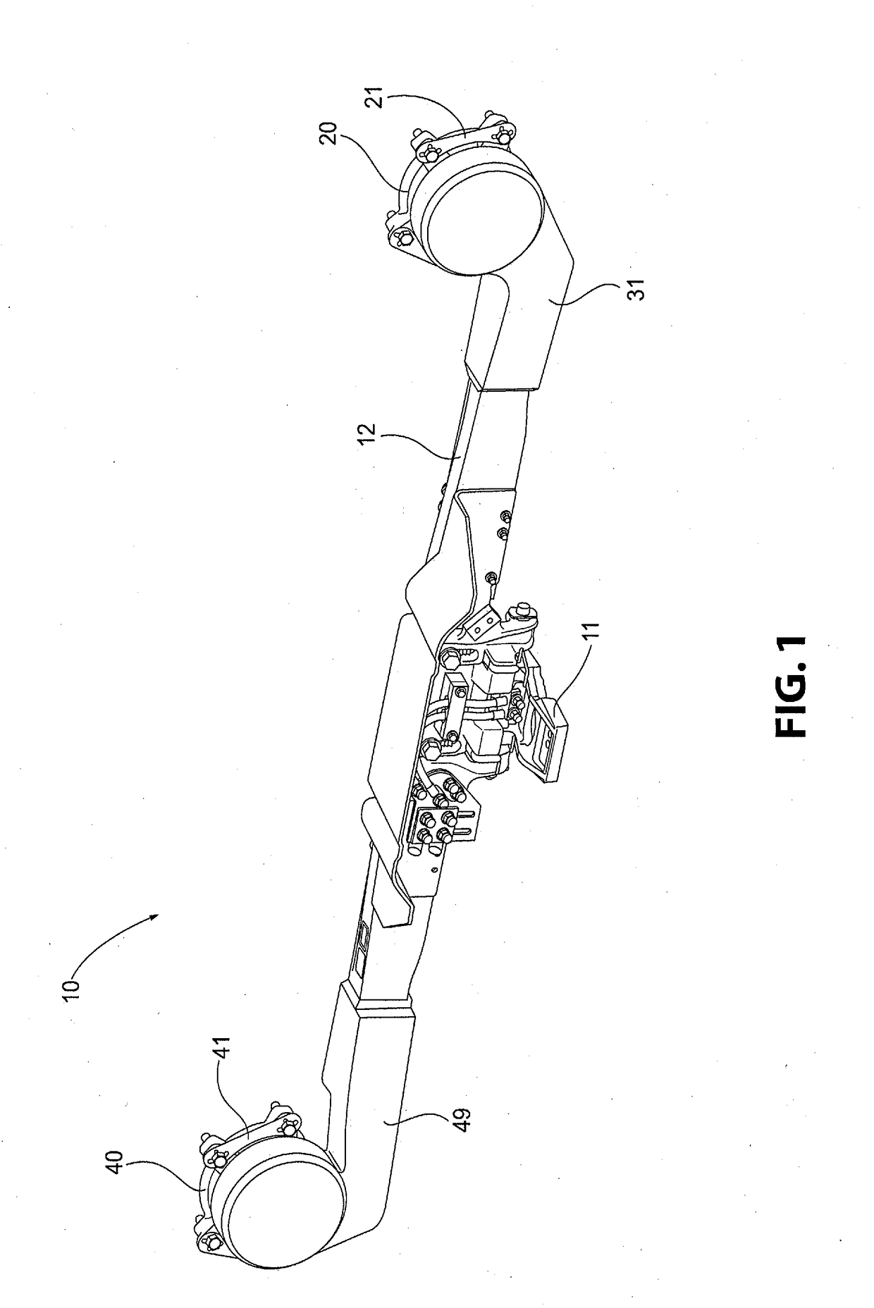
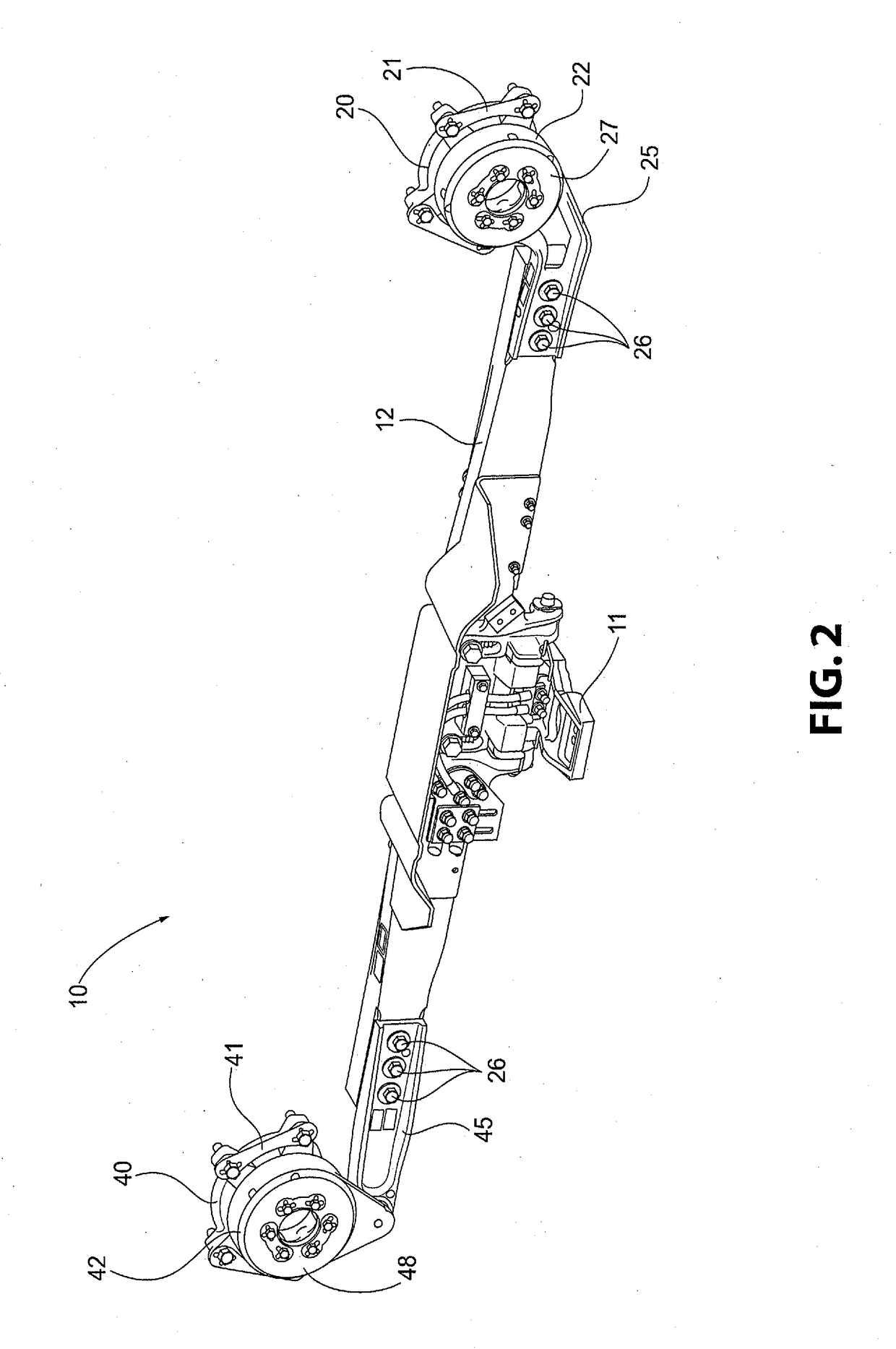
[0034]With reference to FIGS. 1-10, a preferred and non-limiting embodiment or aspect of a current collection device 10 for a rail vehicle in accordance with the principles of the present invention...


PUM


Abstract

An elastomeric element for mounting a current collection device includes an inner hub member; an outer ring defining an exterior annular surface of the elastomeric element; and an intermediate ring of elastomeric material disposed between the inner hub member and the outer ring. The outer ring includes a plurality of segments individually connected to the intermediate ring and wherein the outer ring comprises at least one locking feature configured to be engaged to prevent rotation of the elastomeric element within a housing.

Description

BACKGROUND OF THE INVENTIONField of the Invention[0001]The present invention relates generally to an elastomeric element for mounting a current collection device on a rail vehicle. In particular, the present invention relates to retaining an elastomeric element within a housing connected to the collection device to provide a flexible support for the current collection device on the rail vehicle.Description of Related Art[0002]Current collection devices for communicating electrical current / power to a rail vehicle from an electrified rail, commonly referred to as a “Third Rail”, which are affixed directly to the axle bearing housings of the rail vehicle are generally known in the art. Mounting the device to axle bearing housings provides a more precise relationship to the electrified rail. As the current collection device is affixed directly to the axle bearing housings, elastomeric elements are required to provide flexibility between the mount and the current device.[0003]In prior de...

Claims


Application Information

Patent Timeline
IPC IPC(8): F16F1/38F16M13/02B61F99/00B60L5/39
CPCF16F1/38F16F1/3863F16F1/3856B60L2200/26B61F99/00B60L5/39F16M13/02
Inventor TOOLE, JUSTIN RYANGOLPE, WILLIAM
Owner TRANS TECH OF SOUTH CAROLINA INC
Learn More