
Method for Determining Whether an Individual Enters a Prescribed Virtual Zone Using Skeletal Tracking and 3D Blob Detection

a technology of skeletal tracking and blob detection, applied in the field of patient monitoring systems, can solve the problems of affecting the ability of the detection/monitoring system, increasing the false positive rate of detecting falls, and “at risk, false positives can occur” to achieve the effect of preventing or reducing falls and reducing the impact of falls

Active Publication Date: 2018-03-08
CERNER INNOVATION
View PDF4 Cites 33 Cited by
  • Summary
  • Abstract
  • Description
  • Claims
  • Application Information

AI Technical Summary

Benefits of technology

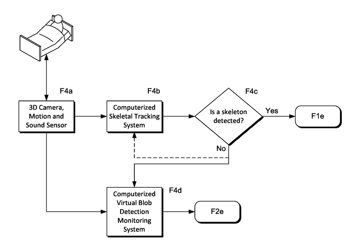
This patent describes a system and method for monitoring people who are disabled, elderly, or at high risk for falls. The system uses a combination of a skeletal tracking system and a virtual blob detection system to detect and prevent falls. The system can also notify medical professionals or caregivers when someone needs assistance. The use of skeletal tracking helps to reduce false positives caused by the virtualblob detection system, and the system can still detect movement even in poor lighting conditions. Overall, this technology can improve safety and reduce harm to vulnerable individuals.

Problems solved by technology

With skeletal tracking alone, there can be factors affecting the cameras / image-video quality which affects the ability of the detection / monitoring system to detect a skeleton.
With blob detection alone, there can be an increase in false positives in detecting falls and “at risk” behavior.
These false positives can occur because blob detection does not differentiate between types of 3D objects.

Method used


Image

  • Method for Determining Whether an Individual Enters a Prescribed Virtual Zone Using Skeletal Tracking and 3D Blob Detection
  • Method for Determining Whether an Individual Enters a Prescribed Virtual Zone Using Skeletal Tracking and 3D Blob Detection
  • Method for Determining Whether an Individual Enters a Prescribed Virtual Zone Using Skeletal Tracking and 3D Blob Detection

Examples


Embodiment Construction

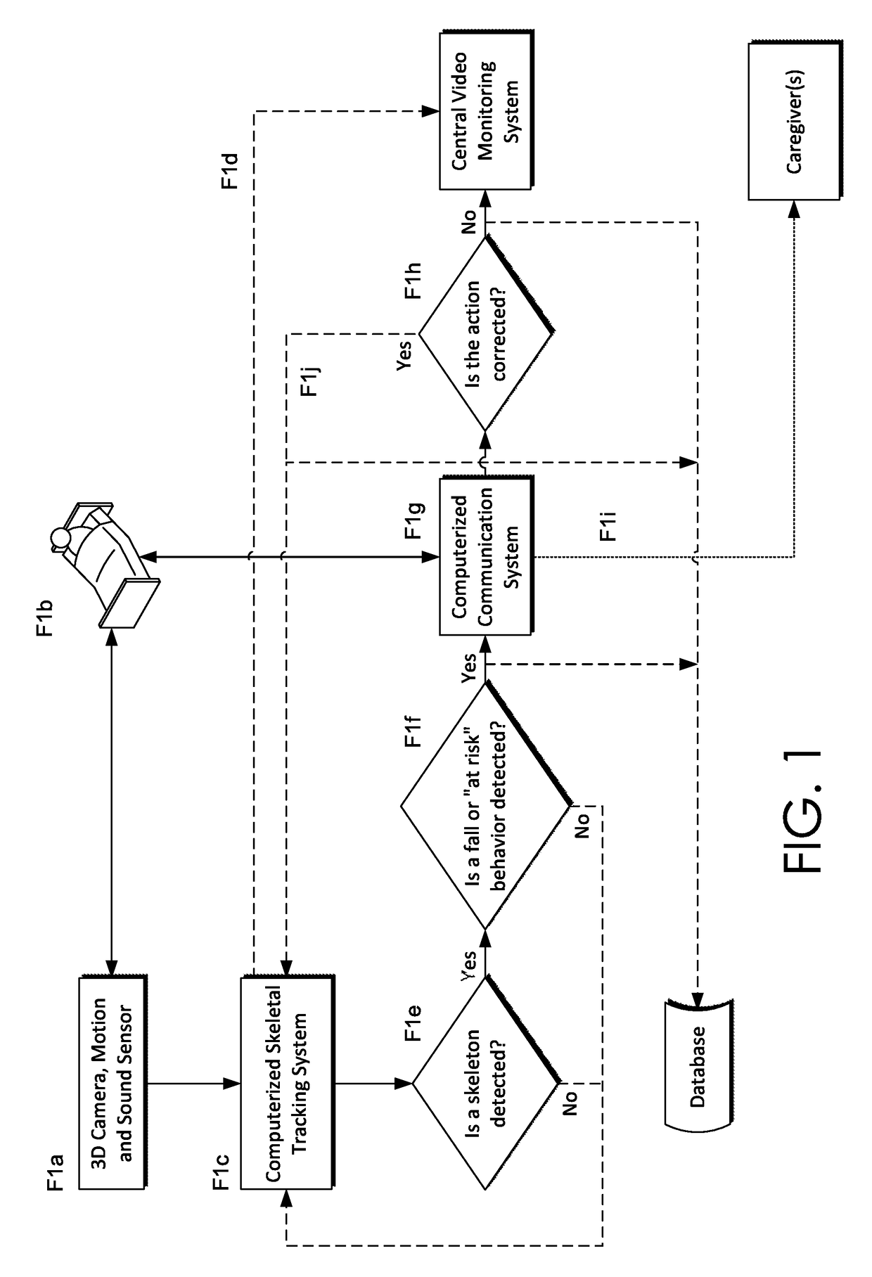
[0017]FIG. 1 illustrates a block diagram for the computerized skeletal tracking configuration, monitoring and alerting system and method of the disclosed system and method. Specifically, FIG. 1 shows the workflow for monitoring an individual's status through the use of one or more 3D Camera, Motion and Sound sensors.

[0018]At step F1a, one or more 3D Camera, Motion and / or Sound sensors can be installed in the patient's or individual's room. At step F1b, the one or more 3D Motion and Sound sensors can be configured to recognize the patient or monitored individual using biometric identifiers such as facial recognition, height, distance between points on the body, etc. The patient's body can be recognized and tracked as one or more skeletal components. Alternatively the patient can be identified by means of a user creating a three-dimensional zone around the patient through a software application stored on the Computerized Skeletal Tracking System or through the use of an electronic tra...


PUM


Abstract

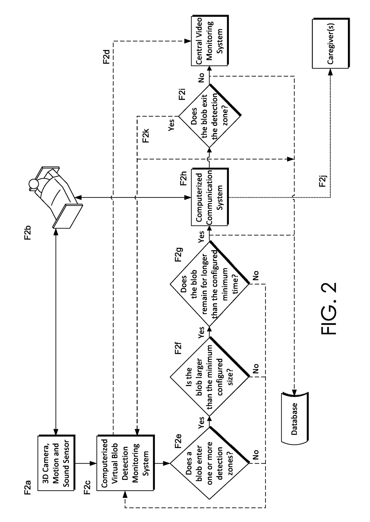
A method and system that allows healthcare providers, hospitals, skilled nursing facilities and other persons to monitor disabled, elderly or other high-risk individuals to prevent or reduce falls and / or mitigate the impact of a fall by delivering automated notification of “at risk” behavior and falls by such an individual being monitored where assistance is required. Two systems are used to identify patients, a skeletal tracking system, which identifies patients by biometric indicators, and a virtual blob detection system. In the virtual blob system, the monitored individual is virtually represented as a blob object of at least a specific size by a computerized monitoring system and such system detects and alerts when the blob object enters or crosses into a virtually defined or designated blob detection zone and remains in the zone for at least a predetermined period of time. These systems may be used concurrently, or one system may be used primarily, with the other system acting as a failsafe.

Description

CROSS-REFERENCE TO RELATED APPLICATION[0001]This application, having attorney docket number CRNI.281516 and entitled “Method for Determining Whether an Individual Enters a Prescribed Virtual Zone Using Skeletal Tracking and 3D Blob Detection,” is a continuation of pending U.S. application Ser. No. 14 / 727,434, filed Jun. 1, 2015 and entitled “Method for Determining Whether an Individual Enters a Prescribed Virtual Zone Using Skeletal Tracking and 3D Blob Detection,” the entirety of which is incorporated by reference herein.FIELD OF THE DISCLOSURE[0002]The present disclosure is generally directed to patient monitoring systems and particularly to a system and method for monitoring patients in a manner which prevents or reduces patient falls.BACKGROUND[0003]According to recent studies, falls are a leading cause of death among people over the age of 65 years and 10% of the fatal falls for patients over 65 years of age occur in a hospital setting. For the general population, studies estim...

Claims


Application Information

Patent Timeline
Patent Type & Authority Applications(United States)
IPC IPC(8): G08B21/04A61B5/11G08B23/00G08B25/14G06T7/20G06K9/32G06K9/00G06V10/34
CPCG06T2207/10021G06K2009/3291A61B5/1128G08B25/14G08B21/043G08B23/00G06K9/3241G06K9/00771G06T7/20A61B5/1117G06T7/246G06V40/103G06V20/53G06V10/34G06V20/52G06V10/62
Inventor KUSENS, NEIL
Owner CERNER INNOVATION
Learn More