Method for mutually controlling and unlocking a dual plug in a lock and a lock with a dual plug

a technology of dual plugs and locks, applied in the field of mutual control and unlocking a dual plug in a lock and a lock with a dual plug, can solve the problems of frequent theft cases and low security, and achieve the effects of increasing lock security, leading the technology, and increasing lock security

Active Publication Date: 2018-03-01
CHU
View PDF23 Cites 4 Cited by
  • Summary
  • Abstract
  • Description
  • Claims
  • Application Information

AI Technical Summary

Benefits of technology

[0056]3. A delayer is further provided between the lock body and the control mechanism; when the first plug translates to the second position in the position difference direction, the control mechanism pushes and compresses the delayer to store energy; when the first plug and the second plug rotate synchronously, the delayer keeps the energy and does not push the control mechanism to return; if the first plug and the second plug do not rotate, the delayer releases energy and pushes the control mechanism to return to the position to control the second lock mechanism in a preset period. The present invention applies delay controlling, greatly increasing the lock security.
[0057]4. The present invention applies a new idea and a new method by changing position difference to time difference, which is new in the lock industry and has a leading position in the technology. The second plug can be unlocked only if the first plug translates to the second position (the position difference), and the translation of the first plug takes time (time difference); during this time period, there are a plurality of restrict conditions; in detailed, at the time the first plug pushes in, the gate of the entrance of the key hole is gradually closed, the delayer stores energy, the second plug can be unlocked after the first plug pushes to the second position, at this time, the gate is partially closed or completely closed, providing no passage for a person to stir the lock; at the same time, the delayer starts to work, the unlocking period is restricted to the time the delayer sets; if the time is out, the delayer releases energy, making the second plug reset to an invalid unlocking state. Therefore, the present invention presents technical unlocking by the time-space conversion, thus greatly increasing the lock security.

Problems solved by technology

The traditional pin tumbler locks have many shortcomings, resulting in low security and frequent theft cases.

Method used


Image

  • Method for mutually controlling and unlocking a dual plug in a lock and a lock with a dual plug
  • Method for mutually controlling and unlocking a dual plug in a lock and a lock with a dual plug
  • Method for mutually controlling and unlocking a dual plug in a lock and a lock with a dual plug

Examples


first embodiment

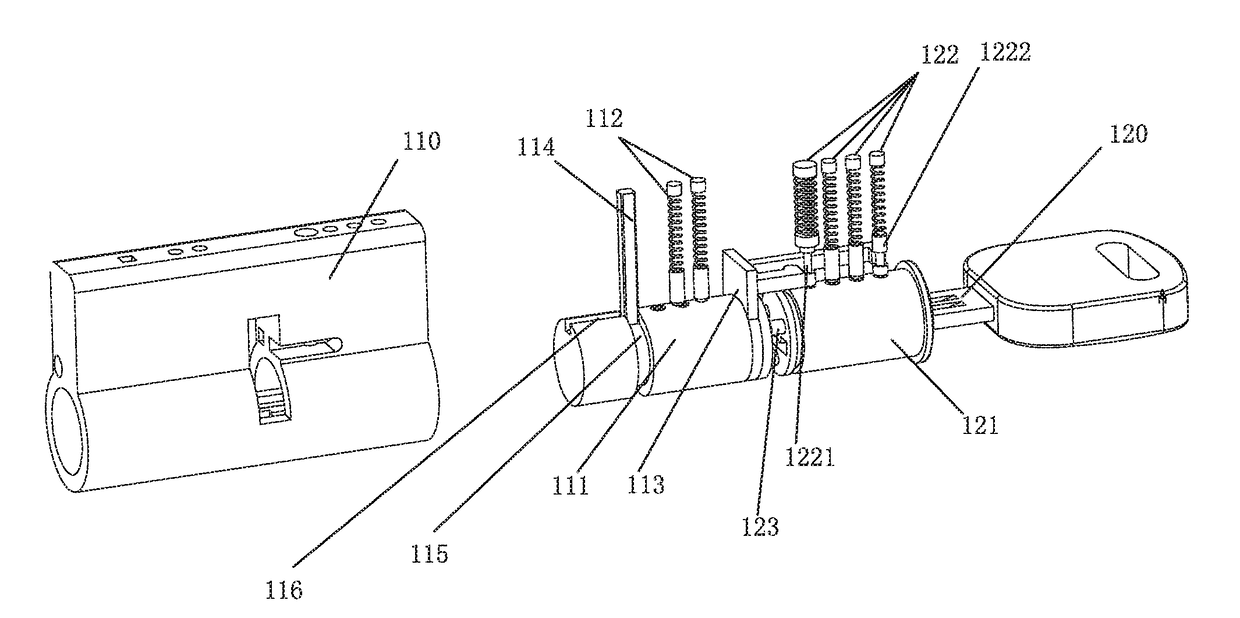
[0163]Referring to FIG. 1, an embodiment of the method according to the present invention is described using a first plug and a second plug utilizing a pin plug structure.

[0164]The lock of the present invention provides a dual plug, having a first plug 111 and a second plug 121. A first pin structure 112 is used to lock and unlock the first plug 111. When the first pin structure 112 locks, it locks between the first plug 111 and a lock body 110. The first plug 111 is unable to rotate. When the first pin structure 112 of the first plug 111 unlocks, assuming that there is no other lock, the first plug 111 is rotatable. Likewise, a second pin structure 122 is used to lock and unlock the second plug 121. When the second pin structure 122 locks, it locks between the second plug 121 and the lock body 110, the second plug 121 is unable to rotate. When the second pin structure 122 of the second plug 121 unlocks, assuming that there is no other lock, the second plug 121 is rotatable.

[0165]Th...

second embodiment

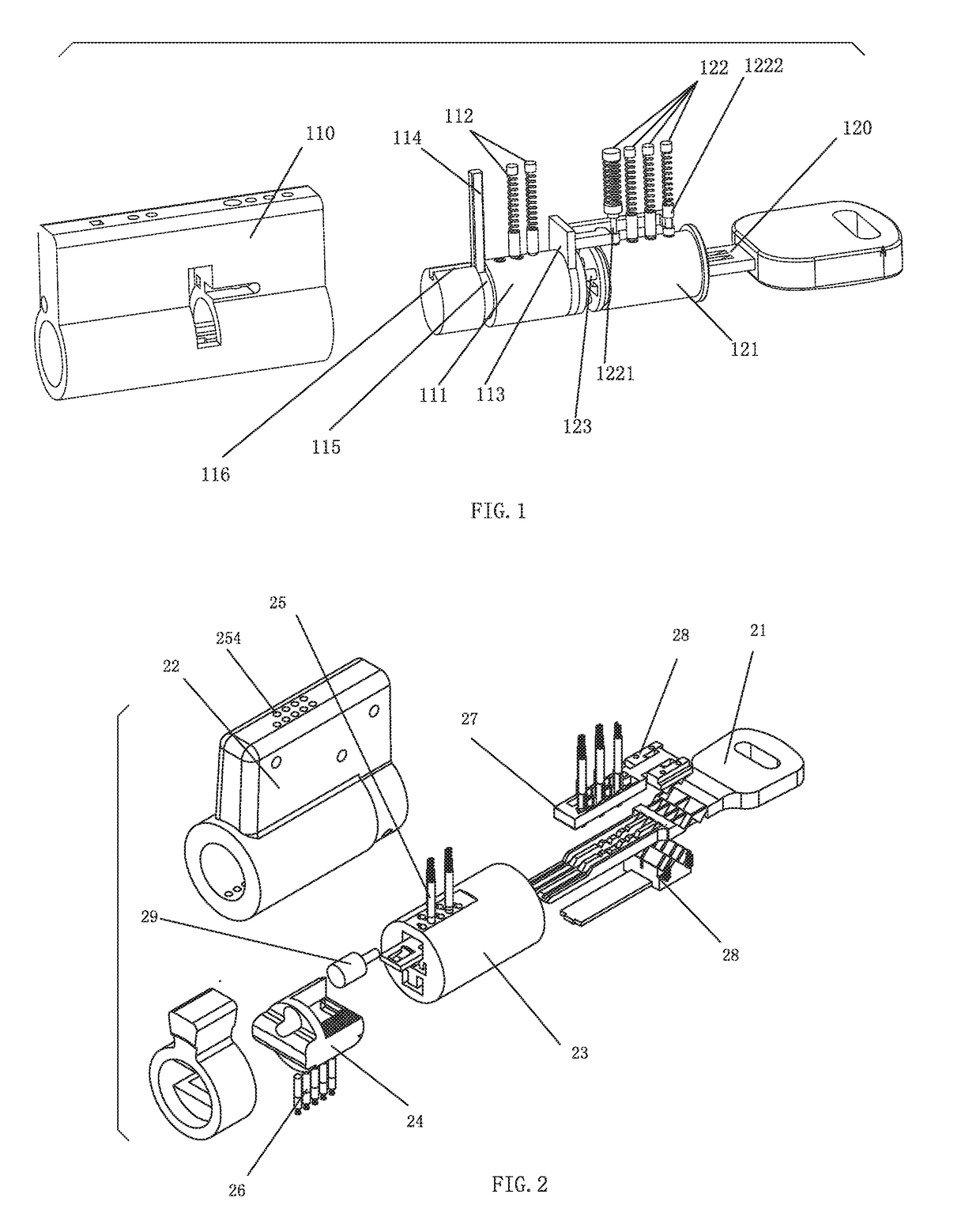
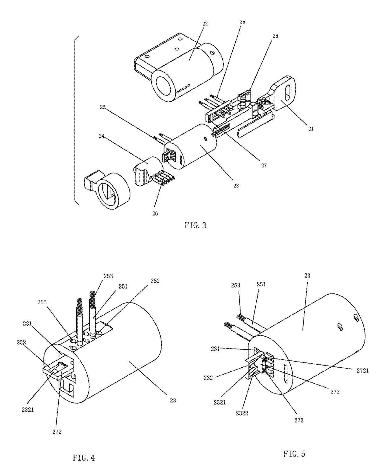
[0185]Referring to FIGS. 2-20, a lock with a dual plug comprises a lock head and a key 21; the lock head comprises a lock body 22, a first plug 24 and a second plug 23; the first and second plugs are rotatably assembled in the lock body 22; a first lock mechanism 26 and a second lock mechanism 25, which can be unlocked by the key, are respectively assembled between the first plug 26, the second plug 25 and the lock body 22 so as to restrict the rotating of the first plug 24 and the second plug 23 in relation to the lock body 22; the first plug 24 and the second plug 23 are mutually controllably connected; the first plug 24 is disposed with a control mechanism 27 to control the second plug 23, the first plug 24 is disposed with a preset position difference; before the first plug 24 translates to the second position, the second lock mechanism 25 is unable to be unlocked; when the key 21 is inserted into the key hole, the key unlocks the first lock mechanism 26 first, then the key 21 p...

third embodiment

[0210]Referring to FIGS. 21-33, the lock with dual plug of the present invention comprises a lock head and a key 310; the lock head comprises a lock body 31 and a plug; the plug is rotatably assembled in the lock body 31; the plug comprises an upper plug 321 (the second plug) and a lower plug 322 (the first plug), the lower plug 322 can move in the lock body 31 axially; an upper lock mechanism 33 (the second lock mechanism) is assembled between the upper plug 321 and the lock body 31; a lower lock mechanism 34 (the first lock mechanism) is assembled between the lower plug 322 and the lock body 31; the key 310 is disposed with an upper and lower key groove to respectively unlock the upper and lower lock mechanism; the lower plug 322 further comprises a control mechanism to control the upper lock mechanism 33; before the lower plug translates to the second position axially, the upper lock mechanism 33 can not be unlocked; when the key 310 is inserted into the key hole, the lower key g...


PUM


Abstract

A method for mutually controlling and unlocking a dual plug in a lock includes: unlocking a code of a first plug first, the first plug restricting unlocking of a second plug, the second plug restricting rotating of the first plug before the code of the first plug is unlocked. after unlocking the code of the first plug, the first plug translating to a second position from a first position using a preset position difference, the first plug being unable to rotate during the translation; after moving the first plug to the second position, the first plug releasing a restriction on the second plug, the second plug still restricting the rotating of the first plug; and unlocking the code of the second plug, the first plug and the second plug being able to rotate synchronously so as to unlock the lock after unlocking the code of the second plug.

Description

TECHNICAL FIELD[0001]The present invention relates to a lock with dual plug, particularly to method for mutually controlling and unlocking a dual plug in a lock and a lock with a dual plug.BACKGROUND[0002]Pin tumbler locks are most widely used in the various locks that are recently available. The pin tumbler locks have many shortcomings in practical use as they are easily unlocked by specialized key picking devices. The unlocking methods are simple: a person uses a steel hook to stir the pins between the lock body and the plug to the coupling surface between the plug and the lock body one by one, and then rotates the plug to unlock the lock. A key with tinfoil can also be used to insert into the lock hole, after shaking, the tinfoil is printed by the pins to make the pin drop to the coupling surface of the plug and the lock body, and the spindle can be rotated to unlock the lock. Another method is to shock or stir the pins back and forth by a toothed device. Some illegal lock pickin...

Claims


Application Information

Patent Timeline
Patent Type & Authority Applications(United States)
IPC IPC(8): E05B27/00E05B35/14E05B17/14E05B43/00
CPCE05B27/0075E05B35/14E05B27/0046E05B17/142E05B43/00E05B2043/007E05B19/0052E05B27/00E05B27/001E05B27/0017E05B29/0026E05B17/14E05B29/0066E05B29/006
Inventor CHU
Owner CHU
Why Eureka
Try Eureka