Trigger type electronic anti-theft lock

An electronic anti-theft lock and trigger technology, which is applied in the field of locks, can solve the problems that the electronic trigger mechanism is greatly affected by the outside world, the key torque of the self-spring lock body is large, and it is inconvenient for the elderly and children to operate, so as to optimize the key unlocking experience and eliminate the need for unlocking. Impact sound, increase the locking point effect of the lock body

Inactive Publication Date: 2018-12-21
YANTAI TRICIRCLE LOCK INDUSTRY GROUP CO LTD
View PDF0 Cites 0 Cited by
  • Summary
  • Abstract
  • Description
  • Claims
  • Application Information

AI Technical Summary

Problems solved by technology

However, the locking method of the lockset still stays on the way of locking the key or lifting the handle, which is not only cumbersome to operate, but also has the potential safety hazard of forgetting to lock it when going out.
In addition, the existing common anti-theft locks are not suitable for aluminum profile anti-theft doors due to the large width and thickness of the lock body. Trigger locking locks have a good development advantage
[0003] At present, there are some electronic trigger locks on the market. Although it solves the cumbersome manual locking, there are certain safety risks. The electronic trigger mechanism is relatively affected by the outside world, and its work is not reliable.

Method used


Image

  • Trigger type electronic anti-theft lock
  • Trigger type electronic anti-theft lock
  • Trigger type electronic anti-theft lock

Examples


Embodiment 1

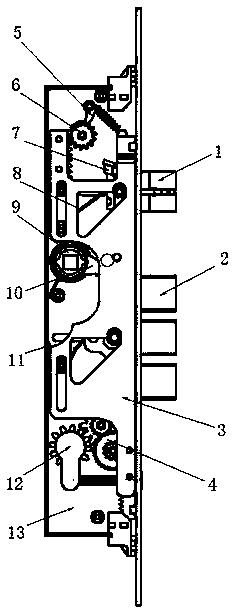
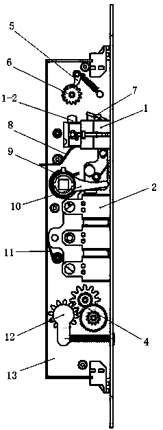
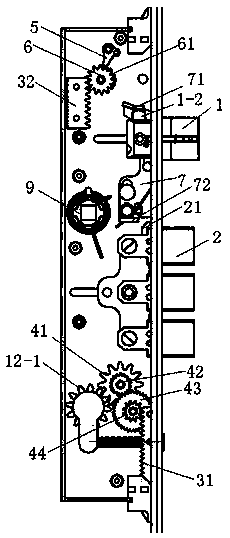
[0028]A trigger type electronic anti-theft lock, which is installed on the door body, cooperates with the tongue groove of the door frame strike plate through the expansion and contraction of the lock body bolt, so as to realize the opening and closing of the lock body. Component 1, dead tongue component 2, main lock plate 3, trigger mechanism, handle shift block 9, idle lock cylinder 12, anti-back ratchet pawl mechanism and key unlocking deceleration mechanism; wherein, the oblique bolt component 1 and the dead tongue component 2 are The oblique tongue torsion spring 8 and the dead tongue torsion spring 11 are elastically pressed into the lock body; the handle dial 9 is also elastically pressed into the lock body through the dial torsion spring. The main lock plate 3 is slidably installed inside the lock body and is linked with the bolt assembly 1 and the dead bolt assembly 2 at the same time. The main lock plate 3 has several driving modes such as handle drive, key drive or e...


PUM


Abstract

The invention relates to a trigger type electronic anti-theft lock. The trigger type electronic anti-theft lock is characterized by comprising a triggering plate which is linked to a latch bolt assembly and a fool bolt assembly at the same time, the triggering plate is installed on a lock body bottom plate in a sliding manner and is provided with a triggering end triggered by the latch bolt assembly, and a locking end used for locking the fool bolt assembly in the lock body; and the tail portion of the latch bolt assembly is provided with a triggering point, when the latch bolt completely stretches out, the triggering point can act on the triggering end of the triggering plate and make the triggering plate slide by a preset distance, and the preset distance should meet the condition that the locking end at the other end of the triggering plate is disengaged from the fool bolt assembly and locks the fool bolt assembly. By means of the trigger type electronic anti-theft lock, a triggering mechanism is arranged between the latch bolt assembly and the fool bolt assembly, automatic locking of the lock body is achieved during door closing, the user experience is good, the trouble of conducting locking through a key or a handle is saved when people go out, in addition, safety and reliability are achieved, and the safety risk that people forget to conduct locking when go out is lowered.

Description

technical field [0001] The invention relates to an anti-theft lock, in particular to a trigger type electronic anti-theft lock, which belongs to the technical field of locks. Background technique [0002] With the gradual development of locks in the direction of intelligence, the opening methods of locks are becoming more and more diverse. For example, passwords, card swipes, fingerprints, iris, etc. are widely used in the industry. Because of their simple and flexible operation, they are favored by users. Gradually replaced the cumbersome way of traditional key unlocking. However, the locking mode of the lockset still stays on the mode of locking the key or locking the handle, which is not only cumbersome to operate, but also has the potential safety hazard of forgetting to lock when going out. In addition, the existing common anti-theft locks are not suitable for aluminum profile anti-theft doors due to the large width and thickness of the lock body. Trigger locking lo...

Claims


Application Information

Patent Timeline
Patent Type & Authority Applications(China)
IPC IPC(8): E05B55/00E05B59/00E05B47/00E05B3/00E05B15/00E05B15/10E05B63/04E05B17/00
CPCE05B55/00E05B3/00E05B15/00E05B15/10E05B15/108E05B17/0045E05B47/0001E05B59/00E05B63/04
Inventor 张书亮涂文军邹江磊杨先明许艳梅吕金美逄东庆
Owner YANTAI TRICIRCLE LOCK INDUSTRY GROUP CO LTD
Why Eureka
Try Eureka