
Battery pack

a battery pack and battery technology, applied in the field of batteries, can solve the problems of affecting the cooling effect of battery cells per unit time, degrading the cooling performance affecting the cooling efficiency of the battery pack, etc., to achieve the effect of improving the cooling efficiency of the cooling duct, short time, and small sealing area

Active Publication Date: 2018-02-15
LG ENERGY SOLUTION LTD
View PDF7 Cites 5 Cited by
  • Summary
  • Abstract
  • Description
  • Claims
  • Application Information

AI Technical Summary

Benefits of technology

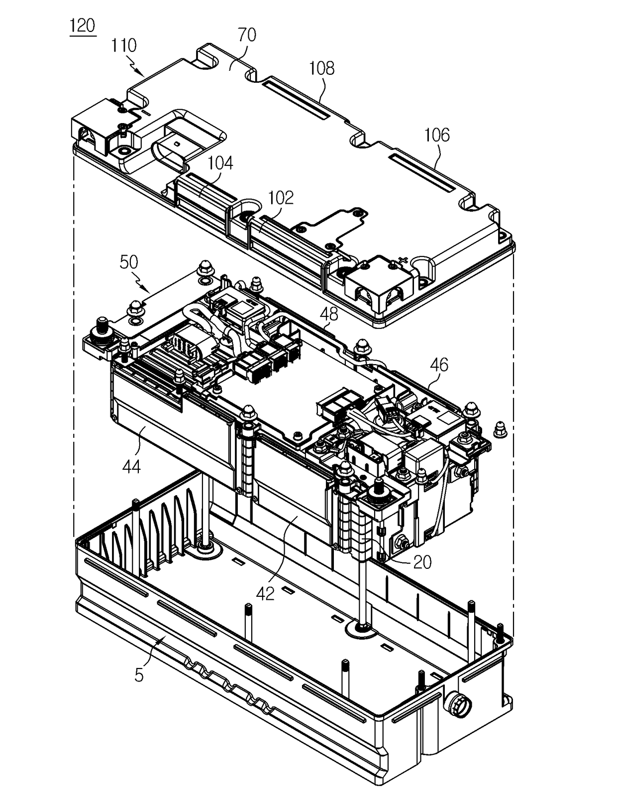
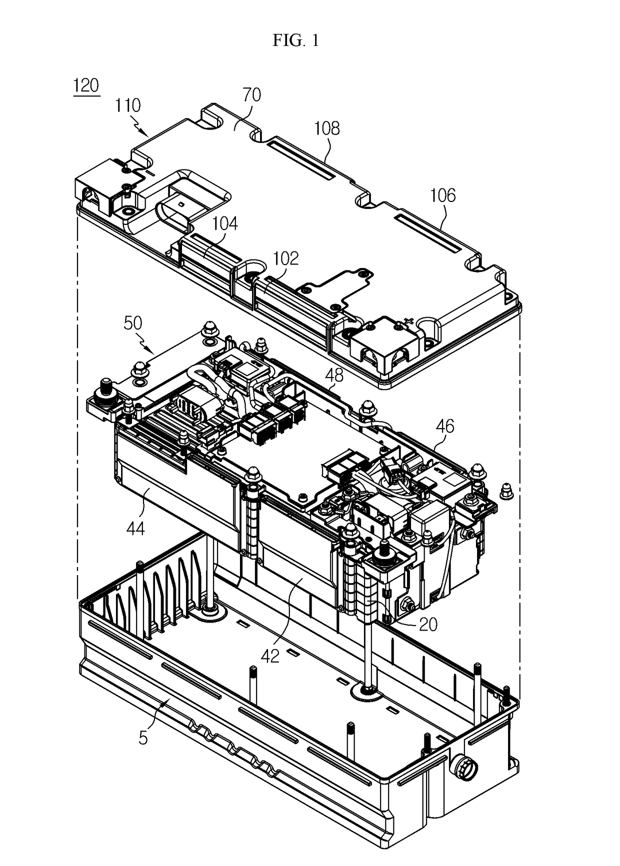
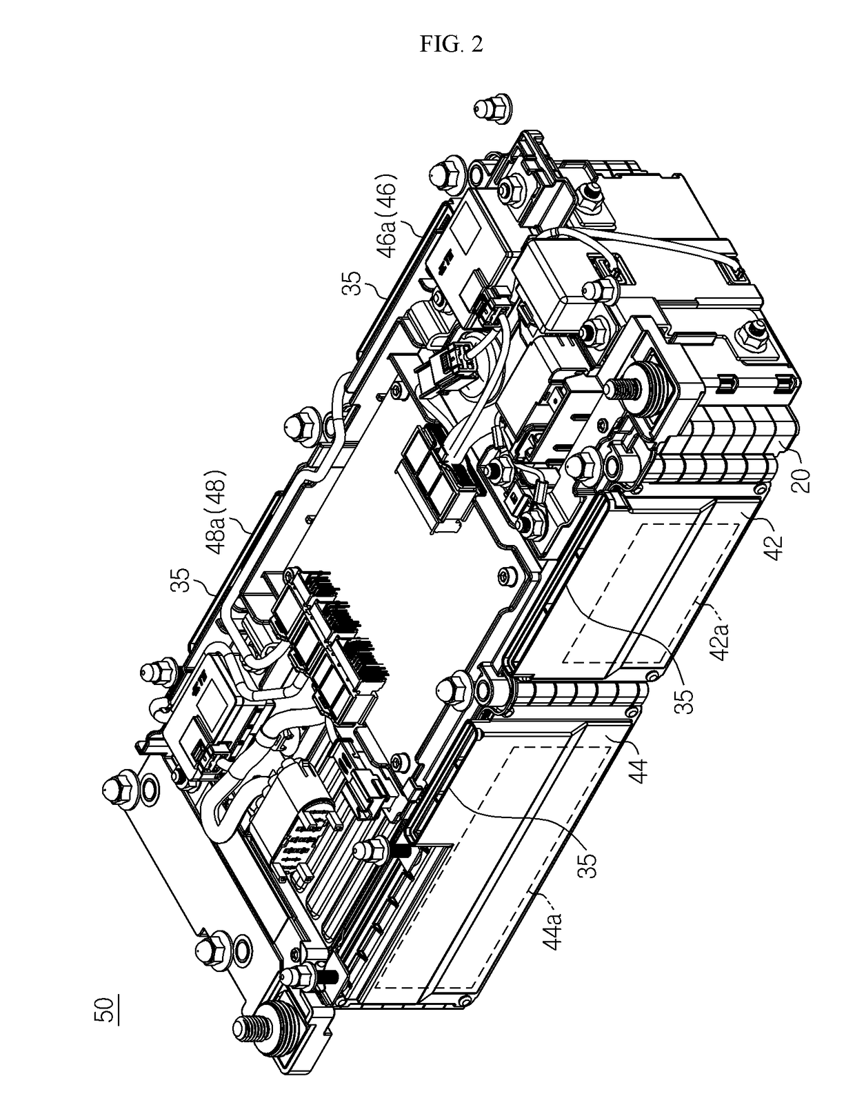
The present disclosure provides a battery pack with improved cooling efficiency and reduced internal pressure during operation. The battery pack includes a sealing member that is located at the end of the lower case and the beginning of the upper case, which minimizes the sealing area between the two cases. The battery pack also includes cooling ducts located on both sides of the battery module and vent structures that communicate with the cooling ducts. These features enable the battery pack to quickly introduce and discharge air into different regions of the upper case, reducing the time needed to cool the battery cells. Overall, the present disclosure enhances the performance and reliability of battery packs.

Problems solved by technology

However, if the cooling duct and the upper case are not matched, the cooling duct and the upper case have an unnecessary space between the cooling duct and the sealing member or between the sealing member and the upper case.
The unnecessary space partially discharges the air to be introduced into the battery module via the cooling duct, thereby degrading the cooling performance of the cooling duct.
Accordingly, a shape of the cooling duct installed between the lower case and the upper case greatly affects cooling effects of battery cells per unit time.
However, in the case of the battery pack, the outside air sequentially passes through the inlet cover, the inlet duct, the battery cells of the cell module, the outlet duct, and the outlet cover, so that battery cells located near the outlet cover may accumulate heat under the influence of hot air that has exchanged heat with other battery cells.
The heat accumulation of some of the battery cells deteriorates electrical characteristics of the battery module.

Method used


Image

  • Battery pack
  • Battery pack
  • Battery pack

Examples


Embodiment Construction

[0045]Hereinafter, preferred embodiments of the present disclosure will be described in detail with reference to the accompanying drawings. Prior to the description, it should be understood that the terms used in the specification and the appended claims should not be construed as limited to general and dictionary meanings, but interpreted based on the meanings and concepts corresponding to technical aspects of the present disclosure on the basis of the principle that the inventor is allowed to define terms appropriately for the best explanation. Therefore, the description proposed herein is just a preferable example for the purpose of illustrations only, not intended to limit the scope of the disclosure, so it should be understood that other equivalents and modifications could be made thereto without departing from the scope of the disclosure.

[0046]In the embodiments described below, a battery cell refers to a lithium secondary battery. Here, the lithium secondary battery is collec...


PUM

PropertyMeasurementUnit
distanceaaaaaaaaaa
heightaaaaaaaaaa
poweraaaaaaaaaa

Abstract

The present disclosure discloses a battery pack suitable for improving cooling efficiency of a cooling duct for battery cells in a battery module by reducing a sealing area between a lower case and an upper case configured to fully surround the battery module. The battery pack according to the present disclosure includes a battery module including battery cells sequentially stacked and a cooling duct located on side of the battery cells; a lower case configured to load the battery module and the cooling duct therein; and an upper case coupled to the lower case so as to cover the battery module and the cooling duct, the upper case having a vent structure on the cooling duct. The vent structure has, on the cooling duct, an inner air passage unit opened at a sidewall of the upper case, and an outer air passage unit inserted into the inner air passage unit.

Description

TECHNICAL FIELD[0001]The present application claims priority to Korean Patent Application No. 10-2015-0085238 filed on Jun. 16, 2015 in the Republic of Korea, the disclosure of which is incorporated herein by reference.[0002]The present disclosure relates to a battery pack suitable for improving cooling effects of an internal structure by flattening sealing surfaces of external structures to sufficiently surround the internal structure by using the external structures.BACKGROUND ART[0003]Recently, to reduce air pollution caused by exhaust gas of vehicles, the vehicles are being manufactured on the basis of research to ensure driving force by using an internal-combustion engine and / or an electric motor. Thus, the vehicles have evolved in the order of a hybrid vehicle, a plug-in hybrid vehicle, and an electric vehicle. In this case, the hybrid vehicle and the plug-in hybrid vehicle have an internal-combustion engine, an electric vehicle, and a battery pack, and the electric vehicle ha...

Claims


Application Information

Patent Timeline
Patent Type & Authority Applications(United States)
IPC IPC(8): H01M2/10H01M10/655H01M2/12H01M10/625H01M10/6557H01M10/6563H01M10/613H01M10/04H01M50/204H01M50/289H01M50/35
CPCH01M2/10H01M10/613H01M10/655H01M10/0413H01M10/625H01M10/6557H01M10/6563H01M2/1077H01M2/12H01M2/043H01M2/1252H01M2220/20H01M10/6556H01M50/289H01M50/204H01M10/6551Y02E60/10Y02P70/50H01M50/30
Inventor LEE, GANG-UJEONG, SANG-YOONSEONG, JUN-YEOBKIM, KI-YOUNYU, SUNG-CHUNMOON, DUCK-HEELEE, JUNG-HANGCHOI, YONG-JOON
Owner LG ENERGY SOLUTION LTD
Learn More