Impact energy absorber

Active Publication Date: 2018-02-15
AXTONE SPOLKA AKCYJNA
View PDF8 Cites 4 Cited by
  • Summary
  • Abstract
  • Description
  • Claims
  • Application Information

AI Technical Summary

Benefits of technology

The invention is a device that absorbs impact energy during machining to increase its rigidity and allow for greater lateral forces. The device comprises two parallel rods connected by mounting plates, and a thrust element to transmit tractive force. The device can be used as a coupler assembly for rail carriages by fastening it to neighboring elements using the mounting plates. The thrust element and the combination of the rods and mounting plates make the device easy to assemble and use in extreme operating conditions, while still safely absorbing impact energy.

Problems solved by technology

Known devices perform well their task of absorbing the kinetic energy of impacts but they are unsuitable for a direct application as devices which transmit axial forces, alternating compressive and tensile ones.

Method used


Image

  • Impact energy absorber
  • Impact energy absorber
  • Impact energy absorber

Examples


Embodiment Construction

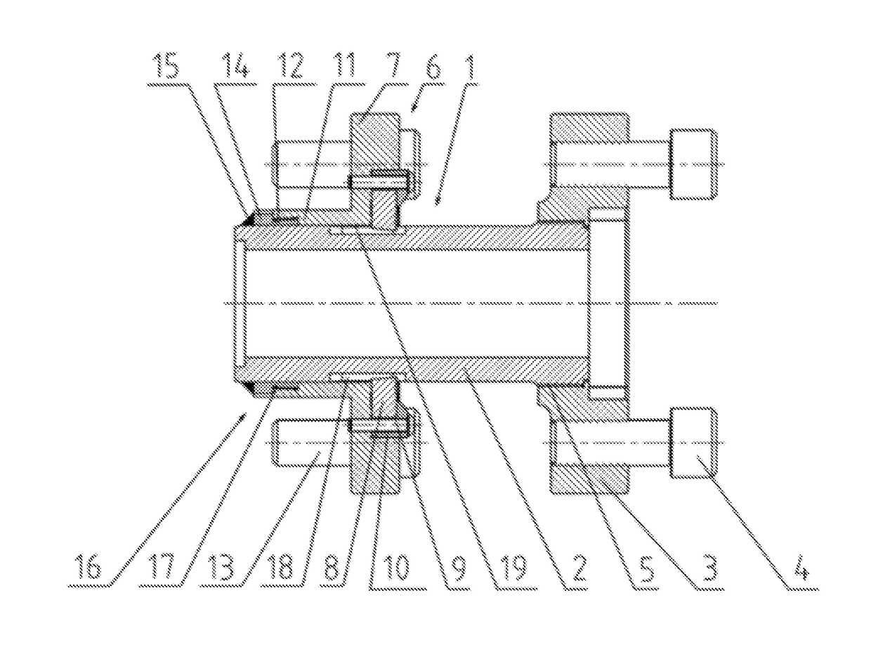
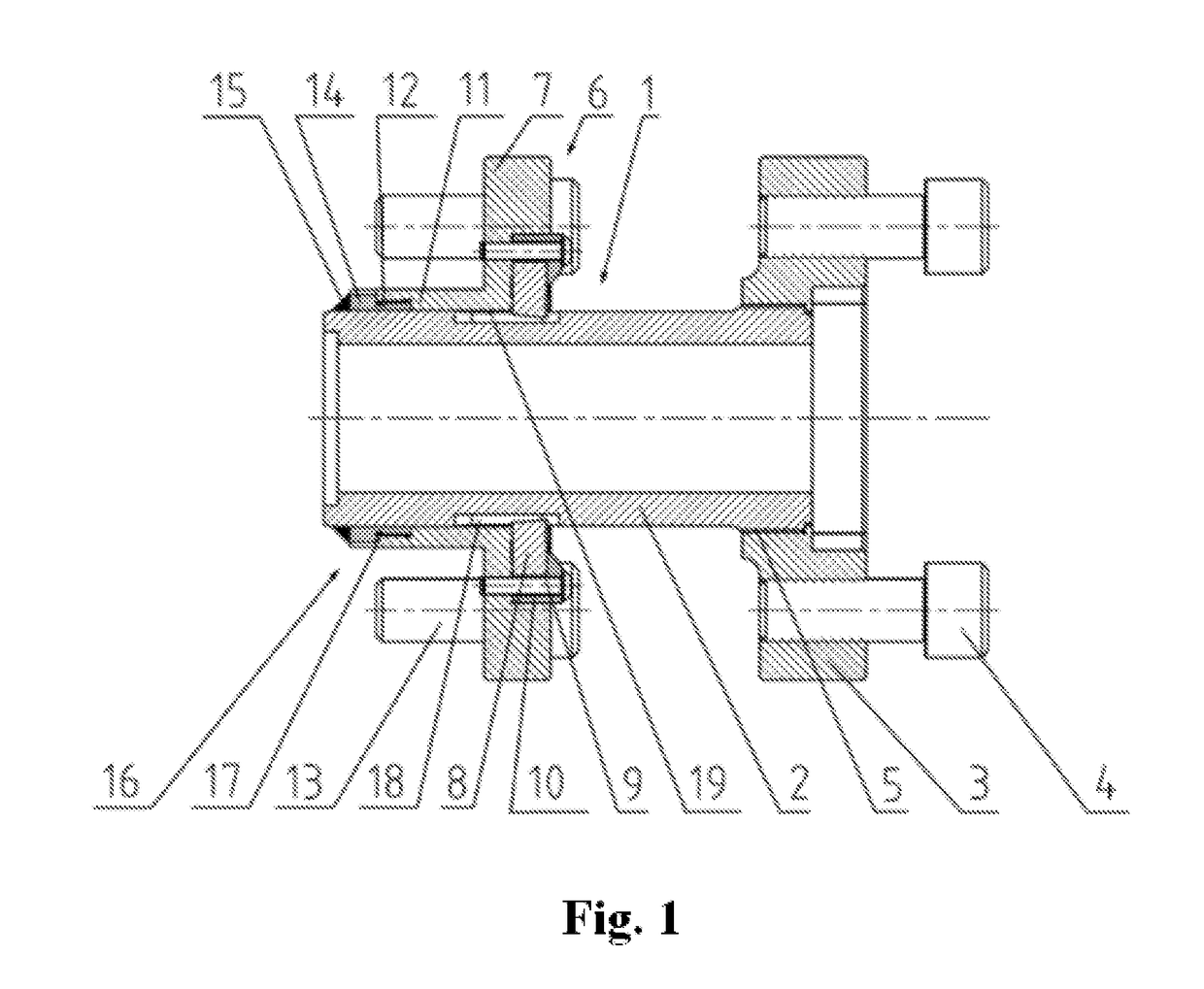
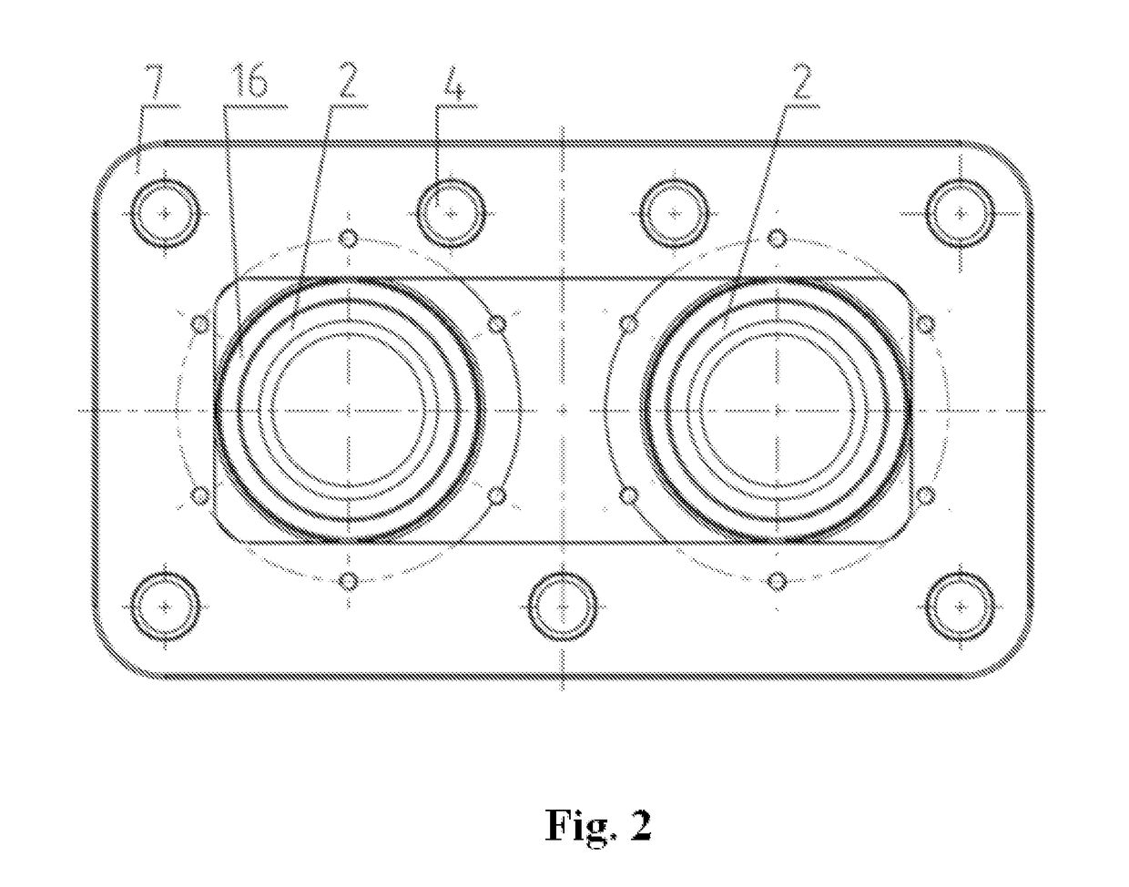
[0042]As presented in the embodiment in FIG. 1 and FIG. 2, the impact energy absorber for structural units connecting rail carriages according to the invention comprises an energy absorbing element 1 which is a set of two steel rods 2 made in the form of machinable sleeves or bars. At one end of each rod 2 there is fastened a mounting plate 3 with bolts 4 which connects the device of the invention with structural units connecting rail carriages. The connection between the mounting plate 3 and the rods 2 is a robust threaded connection 5 which is capable of transmitting both the tractive force and the impact force. This connection is to prevent the shift of the mounting plate 3 relative to the rod 2 at any load conditions. In the vicinity of the other end of each rod 2 there is a machining unit 6 comprising a tool mounting plate 7 with cutting tools 8 placed in the recesses and pressed by bolts 9 via pressure elements 10. The tool mounting plate 7 is fastened to the rods 2 via a slee...


PUM


Abstract

The device contains an energy absorbing element in a form of at least two parallel machinable rods placed at a distance from one another, and at least one thrust element used to transmit a tractive force between the machining unit and the rods. The device also features a tool mounting plate, forming a part of the machining unit, seated on the rods via guiding holes. A mounting plate is fastened on the rods and placed at a distance from the tool mounting plate.

Description

CROSS REFERENCE TO RELATED APPLICATIONS[0001]This application is a national stage application under 35 U.S.C. §371 of International Application No. PCT / IB2016 / 051174, filed Mar. 2, 2016, which claims priority of Polish Patent Application No. P.411483, filed Mar. 5, 2015, the entire contents of each application being herein incorporated by reference.TECHNICAL FIELD[0002]The present invention refers to a device which absorbs impact energy in structural units connecting rail vehicles.BACKGROUND[0003]Patent specification PL202114 presents an impact energy absorber consisting of a rod which can be machined by cutting tools surrounding it, placed evenly in a body sleeve. In order to ensure the correct guiding of the cutting tools, their blades are placed in guides shaped on the outer surface of the rod.[0004]Patent specification PL211405 also presents an impact energy absorber consisting of a rod of a fluently changing diameter, which can be machined by cutting tools. In particular, this ...

Claims


Application Information

Patent Timeline
IPC IPC(8): B61G11/16
CPCB61G11/16F16B5/02F16B5/08
Inventor KUKULSKI, JANWASILEWSKI, LESZEK
Owner AXTONE SPOLKA AKCYJNA
Why Eureka
Try Eureka