
Patient-specific implant flanges with bone side porous ridges

a patient-specific, implant-specific technology, applied in the field of custom-made implants, can solve the problems of patient pain, loosening of implants, damage to artificial joints, etc., and achieve the effect of promoting bone ingrowth

Active Publication Date: 2018-02-08
HOWMEDICA OSTEONICS CORP
View PDF9 Cites 1 Cited by
  • Summary
  • Abstract
  • Description
  • Claims
  • Application Information

AI Technical Summary

Benefits of technology

The patent describes an implant design that includes a base, flanges, and ridges. The implant can be designed using virtual planning and can be made from various metals, plastics, and other materials. The implant can also have holes and ridges that are porous. The technical effects of the implant design include promoting bone growth and securely attaching the implant to the patient's bone.

Problems solved by technology

Over time, artificial joints, in particular hip joints, become damaged due to normal wear and tear of any one or any combination of the prosthetic implant, the bone interfacing with the implant, the bone surrounding the implant, and in more extreme cases, due to infection of the surrounding bone.
In light of the damage, the prosthesis does not fit the bone securely and is ineffective in providing appropriate support and movement for a patient, often causing the patient pain.
Such manual techniques potentially expose the patient to a lack of conformity between the implant and the bone that can lead to loosening of the implant or material debridement caused by movement of the implant due to undesired play between the implant and the bone.
Additionally, implants for these revision systems are provided in a limited number of standard shapes and sizes that may not conform all that closely to a patient's anatomy or that may not have flanges that align with more dense regions of bone for fastening using the bone screws.
These limitations create a higher tendency for future damage or failure earlier than anticipated.
However, the use of augments requires components additional to the main implant and, like the main implant, such augments are substantially inflexible and have screw holes in a standardized configuration that match the screw holes of the portion of the main implant underlying the augments.

Method used


Image

  • Patient-specific implant flanges with bone side porous ridges
  • Patient-specific implant flanges with bone side porous ridges
  • Patient-specific implant flanges with bone side porous ridges

Examples


Embodiment Construction

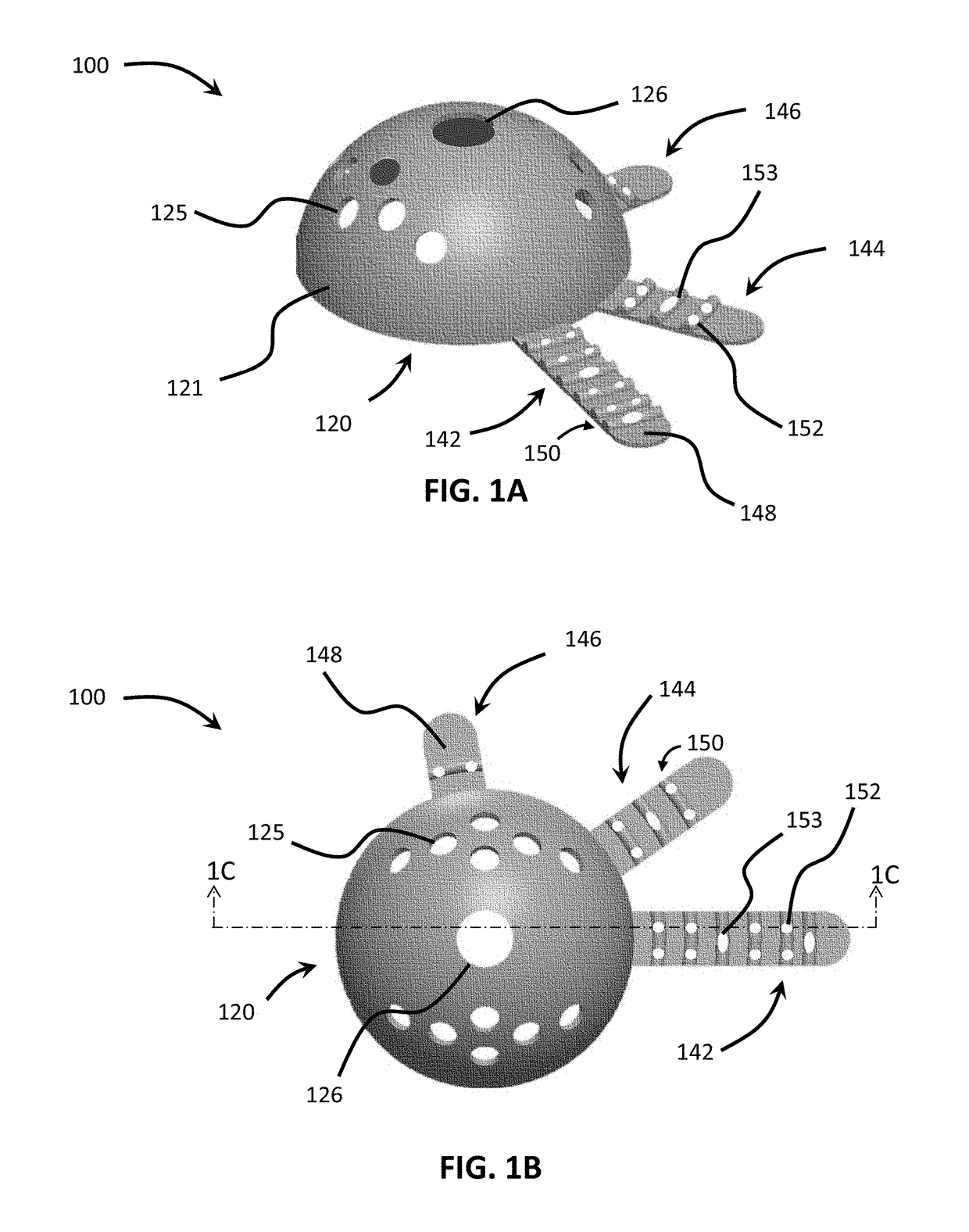
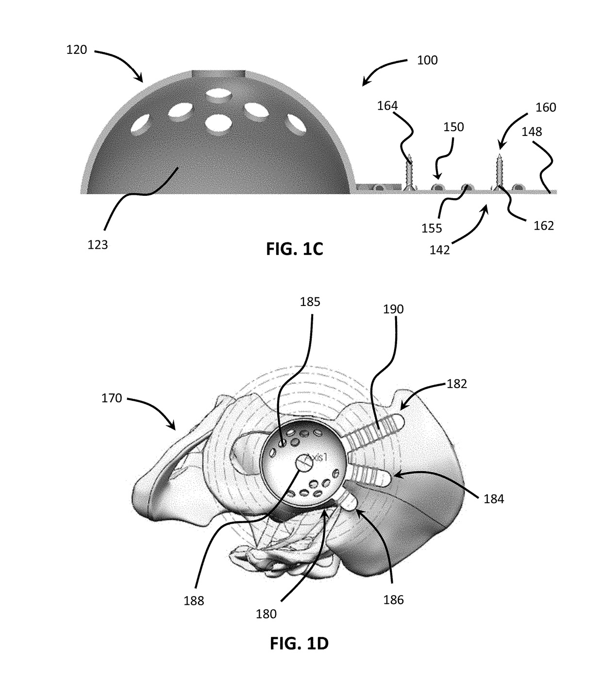
[0045]Referring now to the drawings, as shown in FIGS. 1A-1C, implant 100 may include base 120 and a series of flanges 142, 144, 146 extending from the base. As shown, base 120 may be in the shape of a dome having upper surface 121 and lower surface 123 and may be in the form of an acetabular cup. Upper surface 121 may be convex such that the upper surface may be inserted within a concave surface of bone, such as but not limited to an acetabulum. Lower surface 123 may be concave such that the lower surface may receive another implant. In some arrangements, as shown in implant 100 preferably may be in the form of an acetabular cup shell that lower surface 123 may be configured to receive a bearing insert, which preferably may include a polyethylene or other polymeric bearing as known to those skilled in the art. In other arrangements, the implant may be an acetabular cup for direct receipt of another bone or a prosthesis that replaces the other bone, such as but not limited to a head...


PUM


Abstract

An implant includes a base, a flange, and ridge. The flange extends from the base. The ridge extends from the flange. A hole extends through the flange and the ridge. A system with the implant includes a fastener extending through the ridge of the implant. The implant is placed into bone by securing a base of the implant to a main complementary contact surface of bone and by securing a ridge extending outwardly from a flange of the implant to a secondary complementary contact surface of bone spaced from the main complementary contact surface.

Description

CROSS-REFERENCE TO RELATED APPLICATION[0001]The present application claims the benefit of the filing date of U.S. Provisional Patent Application No. 62 / 369,829 filed Aug. 2, 2016, the disclosure of which is hereby incorporated herein by reference.FIELD OF THE INVENTION[0002]The present invention relates generally to procedures and implants to treat joint failure, and in particular relates to customized implants for surgical revision procedures.BACKGROUND OF THE INVENTION[0003]Over time, artificial joints, in particular hip joints, become damaged due to normal wear and tear of any one or any combination of the prosthetic implant, the bone interfacing with the implant, the bone surrounding the implant, and in more extreme cases, due to infection of the surrounding bone. In light of the damage, the prosthesis does not fit the bone securely and is ineffective in providing appropriate support and movement for a patient, often causing the patient pain. To repair such defects in the case o...

Claims


Application Information

Patent Timeline
Patent Type & Authority Applications(United States)
IPC IPC(8): A61F2/34
CPCA61F2002/3483A61F2002/30774A61F2002/30784A61F2002/30828A61F2002/3432A61F2002/3408A61F2002/30945A61F2/34A61F2002/343A61F2002/3404A61F2/30734A61F2/30942A61F2002/30578A61F2002/30736A61F2002/30777A61F2002/30879A61F2002/3092A61F2002/3096A61F2002/30962A61F2002/3401A61F2002/3403A61F2002/30943
Inventor MISTRY, AMIT
Owner HOWMEDICA OSTEONICS CORP
Learn More