System and Method for Three-Dimensional Mapping using Two-dimensional LiDAR Laser Ranging

a lidar laser and three-dimensional mapping technology, applied in the field of three-dimensional mapping using two-dimensional lidar laser ranging, can solve the problems of not being able to cover a narrow horizontal sliver of the environment, not being able to achieve the effect of eliminating deficiencies

Active Publication Date: 2018-02-01
SHARP KK
View PDF2 Cites 6 Cited by
  • Summary
  • Abstract
  • Description
  • Claims
  • Application Information

AI Technical Summary

Benefits of technology

[0008]Disclosed herein are means to use two-dimensional (2D) light detection and ranging (LiDAR) data to create a three-dimensional (3D) terrain image. The disclosed 2D LiDAR rotational scheme eliminates deficiencies in existing systems to permit the generation of enough 2D data to provide a 3D image of the terrain surrounding an autonomous platform.
[0010]The system and method disclosed herein adds another dimension to the 2D scan by rocking (or “oscillating”) the 2D LiDAR assembly back and forth about some axis that is typically parallel to the scanned plane. By “rocking” the 2D LiDAR assembly about this axis, 3D LiDAR functionality can be delivered without the complexity of slip-ring electrical contacts that are used in many more expensive products. This creates a nearly complete 3D field of view.

Problems solved by technology

This is a functionally limited, but inexpensive and robust device.
In theory, the horizontal sweep can cover a full 360 degrees, but in practice the sweep is usually limited by chassis supporting the laser and mirror.
However, the main limitation is that the sweep only covers a narrow horizontal sliver of the environment.
The fully rotating design can scan a more complete field of view, but it requires a complex mechanical linkage.
Because the laser is a power consuming device these configurations require some means to get power and data onto and off of the spinning LiDAR device.
But without a supplemental charging source the batteries run down, thus limiting service uptime.
Both of these solutions come with increased maintenance requirements and introduce potential failure points.

Method used


Image

  • System and Method for Three-Dimensional Mapping using Two-dimensional LiDAR Laser Ranging
  • System and Method for Three-Dimensional Mapping using Two-dimensional LiDAR Laser Ranging
  • System and Method for Three-Dimensional Mapping using Two-dimensional LiDAR Laser Ranging

Examples


Embodiment Construction

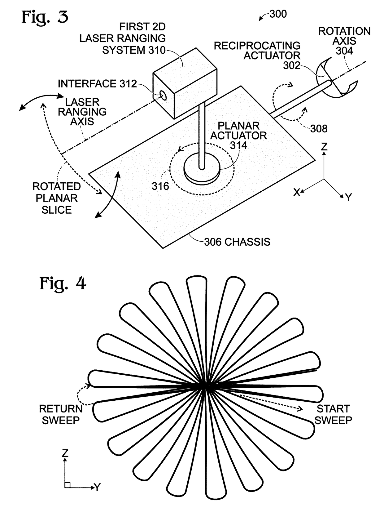
[0026]FIG. 3 is a schematic block diagram of a three-dimensional (3D) LiDAR system using a two-dimensional (2D) LiDAR. The system 300 comprises a reciprocating actuator 302 having a rotation axis 304. A chassis 306 is attached to the reciprocating actuator 302, and is capable of reciprocal rotation about the rotation axis 304. As used herein, a reciprocating actuator is any mechanical means able to create a reciprocating or oscillating mechanical rotational motion. The reciprocating action is represented by the are 308. A first 2D laser ranging system 310 has an (optical) interface 312 for laser ranging a planar slice of an environment, and is mounted in the chassis 306. The simultaneous laser ranging of the planar slice and chassis rotation create a 3D laser mapping of at least a portion of the environment. More explicitly, the first 2D laser ranging system includes a planar actuator 314 for laser ranging a first planar slice, and the reciprocating actuator 302 rotates the chassis ...


PUM


Abstract

A system and method are presented for using a two-dimensional (2D) LiDAR for three dimensional (3D) laser mapping. The 2D-LiDAR is mounted in a chassis. The method laser ranges a planar slice of the environment. Simultaneous with laser ranging the planar slice, the 2D LiDAR chassis is rotated about an axis to create a 3D laser mapping of at least a portion of the environment. More explicitly, the 2D LiDAR may include a laser ranger with a planar actuator, typically the combination of a laser and a rotating mirror. In addition, the 2D LiDAR chassis is mounted on a reciprocating actuator. Thus, the step of laser ranging the planar slice includes laser ranging the planar slice in response to the planar actuator. The step of rotating the 2D LiDAR chassis includes rotating the 2D LiDAR chassis around an axis parallel to the planar slice, in response to the reciprocating actuator.

Description

BACKGROUND OF THE INVENTION1. Field of the Invention[0001]This invention generally relates to environment mapping and, more particularly, to a system and method for modifying a two-dimensional (2D) light detection and ranging (LiDAR) system for use in three-dimensional (3D) mapping.2. Description of the Related Art[0002]A LiDAR is often the primary source of sensor data used by robots for Simultaneous Localization And Mapping (SLAM) reconstruction, obstacle detection and avoidance, feature detection, and scene classification, as well as other applications in the field of mobile robotics. LiDAR uses ultraviolet, visible, or near infrared light to image objects. A fixed 2D LiDAR can be constructed by bouncing a laser beam off a spinning mirror. As with RADAR, the difference in time between transmitted and returned signals determines the distance to, and shape of objects in the environment. This is a functionally limited, but inexpensive and robust device. Fixed 2D LiDAR units are ofte...

Claims


Application Information

Patent Timeline
Patent Type & Authority Applications(United States)
IPC IPC(8): G01S17/89G01S17/42G01S7/481
CPCG01S17/89G01S17/42G01S7/4817
Inventor HAINES, DARINVOJAK, WILLIAMGAEBEL, GARYTHOMAS, JOHN
Owner SHARP KK
Why Eureka
Try Eureka