
Mapping Techniques Using Probe Vehicles

Inactive Publication Date: 2018-01-25
INTELLIGENT TECH INT
View PDF9 Cites 32 Cited by
  • Summary
  • Abstract
  • Description
  • Claims
  • Application Information

AI Technical Summary

Benefits of technology

The invention is a method and system for mapping terrain with roads using a vehicle equipped with a camera and a position determining system. An inertial measurement unit (IMU) is used to provide position and orientation information, which is combined with data from the camera to create maps of the terrain. The use of inexpensive IMU technology and GPS positioning allows for frequent calibration and the determination of accurate position and orientation of the vehicle without the need for self-testing of the accelerometers or gyroscopes. Additional accelerometers and gyroscopes can be used in the device without increased complexity and the use of the Kalman filter or neural network technologies improve the accuracy of calculations and eliminate errors caused by alignment errors.

Problems solved by technology

The silicon crystal typically has residual stresses that can cause the mechanical structure of the accelerometer to change geometrically as a function of time and / or temperature unpredictably.
This adds cost and complexity to the accelerometer and sensor software design.
This self-testing feature also increasingly complicates the device design if more than one axis is simultaneously tested.
Such devices are not used to determine the angular position of cameras.
No admission is made that any or all of these references are prior art and indeed, it is contemplated that they may not be available as prior art.

Method used


Image

  • Mapping Techniques Using Probe Vehicles
  • Mapping Techniques Using Probe Vehicles
  • Mapping Techniques Using Probe Vehicles

Examples


Embodiment Construction

[0026]An object of the present invention is to provide a mapping system for probe vehicles. To do this, basic engineering solutions for a GPS-corrected IMU angular and displacement location system primarily for mass produced cars are presented. This objective is accomplished by:

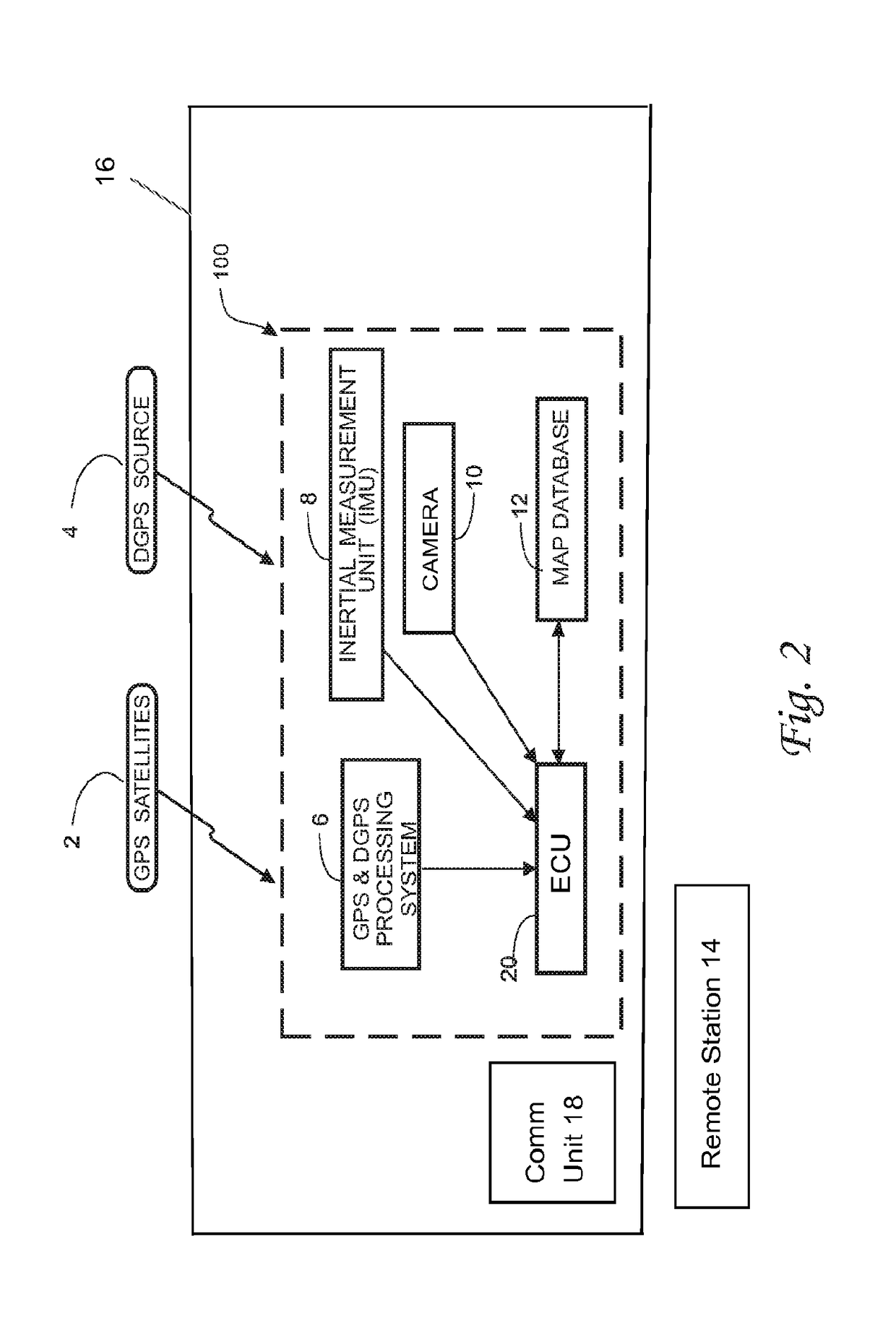
[0027]1) Using a device containing a camera, a GPS or equivalent receiver, communication apparatus, IMU, and an ECU, comprising an electronic control system with the inertial measurement unit (IMU) mounted together at an appropriate location for imaging an area external to the vehicle.

[0028]2) Manufacturing IMUs in accordance with the mass-production MEMS technology at a cost of a few dollars per unit. An IMU can comprise 3 accelerometers and 3 gyroscopes or more generally, a plurality of accelerometers and / or a plurality of gyroscopes. Sometimes, it also comprises a 3 axis magnetometer.

[0029]3) Replacing the expensive, currently in-use self-calibration system for the correction of the changing errors in the ...


PUM


Abstract

Vehicle-mounted device includes an inertial measurement unit (IMU) (8) having at least one accelerometer or gyroscope, a GPS receiver (6), a camera (10) positioned to obtain unobstructed images of an area exterior of the vehicle (16) and a control system (20) coupled to these components. The control system (20) re-calibrates each accelerometer or gyroscope using signals obtained by the GPS receiver (6), and derives information about objects in the images obtained by the camera (10) and location of the objects based on data from the IMU (8) and GPS receiver (6). A communication system (18) communicates the information derived by the control system (20) to a location separate and apart from the vehicle (16). The control system (20) includes a processor that provides a location of the camera (10) and a direction in which the camera (10) is imaging based on data from the IMU corrected based on data from the GPS receiver (6), for use in creating the map database (12). (FIG. 2)

Description

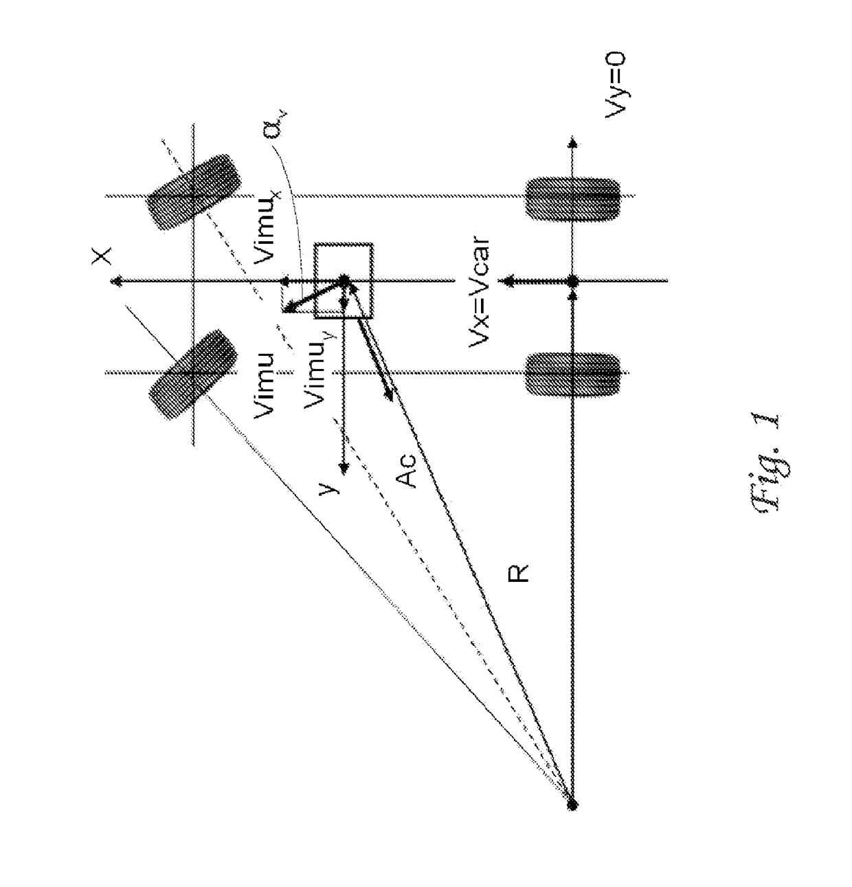
TECHNICAL FIELD[0001]The present invention relates generally to arrangements and methods for mapping terrain including roads using probe vehicles traveling on the roads, wherein each vehicle contains one or more cameras with GPS-corrected IMUs.BACKGROUND ART[0002]A detailed discussion of background information is set forth in U.S. patent application Ser. Nos. 14 / 069,760 and 13 / 686,862.[0003]Electronic crash sensors used to sense crashes for airbag deployment currently in production comprise one or more MEMS accelerometers that measure acceleration at the sensor location. These accelerometers are typically produced by micromachining a single crystal of silicon and the sensing elements are frequently in the form of a beam or tuning fork. The silicon crystal typically has residual stresses that can cause the mechanical structure of the accelerometer to change geometrically as a function of time and / or temperature unpredictably. As a result, properties of the accelerometer similarly can...

Claims


Application Information

Patent Timeline
IPC IPC(8): G08G1/01G08G1/0962B60K31/18G09B29/00G09B29/10B60W30/08G06T7/70G01C21/32
CPCG08G1/0129G06T7/70G08G1/09626G01C21/32G09B29/007G09B29/106B60W30/08B60K31/18G06T2207/30244G06T2207/30252G06T2207/10016B60Y2400/304B60Y2400/301B60Y2400/3015B60R1/00B60R2300/30B60R2300/802B60K2031/0091B60W2400/00B60W2550/402B60W2420/42B60W2550/10G08G1/0112G08G1/0141G01C21/3815G01C21/3848G01C21/3841G01C21/3826B60W2554/00B60W2556/50B60W2420/403
Inventor BREED, DAVID SBREED, RYAN
Owner INTELLIGENT TECH INT
Learn More