
Laser spot light with twinkling function

Active Publication Date: 2018-01-18
XI JUN
View PDF4 Cites 1 Cited by
  • Summary
  • Abstract
  • Description
  • Claims
  • Application Information

AI Technical Summary

Benefits of technology

The present invention relates to outdoor illumination devices, particularly laser spot lights with twinkling function. The technical effect of the invention is to provide a laser spot light with twinkling function, which has not been possible with traditional cartoon laser spot lights. The invention solves the problem of visual fatigue caused by traditional cartoon laser spot lights without twinkling function. The laser spot light has a unique design that includes a body case, heat radiator, laser head, light baffle, first grating, gearbox, and motor. The invention also includes an external cooling device and heat transmission part for dissipating heat generated by the laser head. The technical effect of the invention is to provide a laser spot light with twinkling function that is more visually appealing and less likely to cause visual fatigue.

Problems solved by technology

The disadvantages of the laser spot light with fixed raster images and cartoon laser spot light both include that they have no twinkling effect, and this cause visual fatigue.

Method used


Image

  • Laser spot light with twinkling function
  • Laser spot light with twinkling function
  • Laser spot light with twinkling function

Examples


Embodiment Construction

[0009]The invention will now be described in detail through several embodiments with reference to the accompanying drawings.

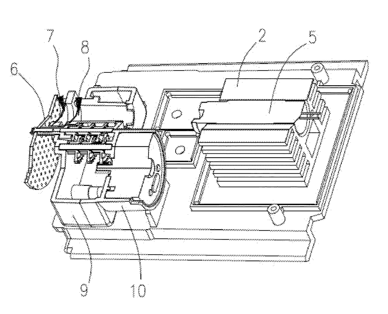
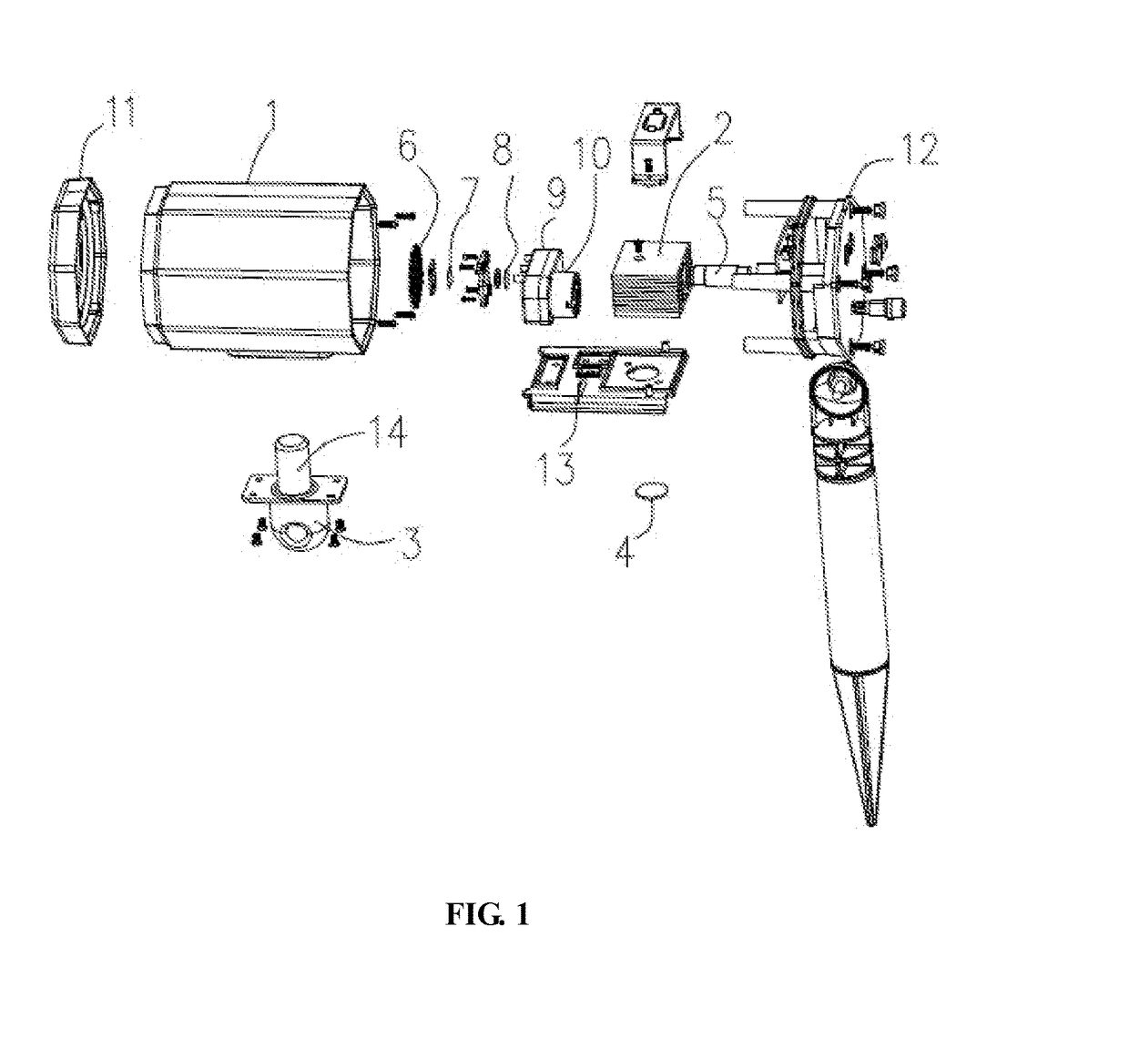
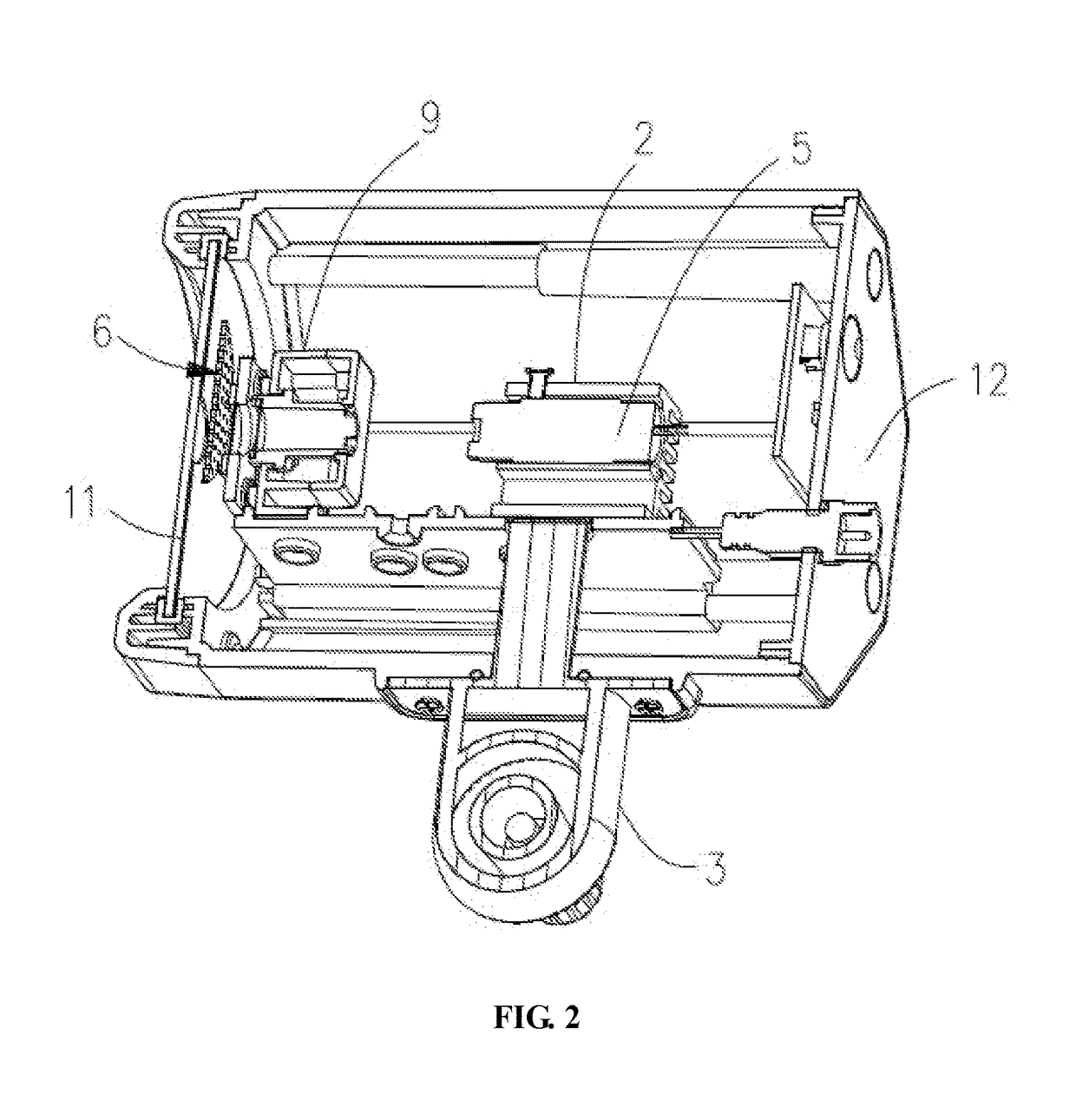
[0010]Please refer to FIG. 1 to FIG. 4, a laser spot light with twinkling function in accordance with an embodiment of the present invention mainly includes a body case 1 housing a heat radiator 2, a laser head 5, a light baffle 6, a first grating 7, a first grating 8, a gearbox 9, and a motor 10. In FIG. 2, a part of the body case 1, the heat radiator 2, the laser head 5, the light baffle 6, the first grating 7, the first grating 8, and the gearbox 9 is cut away, and the motor 10 is not shown. In FIG. 3, a part of the heat radiator 2, the laser head 5, the light baffle 6, the first grating 7, the first grating 8, the gearbox 9 and the motor 10 is cut away from another view. In FIG. 4, the light baffle 6, the first grating 7, the first grating 8, the gearbox 9 and the motor 10 is cut away.

[0011]The body case 1 is substantially a hollow cylinder. An end of the c...


PUM


Abstract

The present invention provides a laser spot light with twinkling function including a laser head, a body case defining an opening, a heat radiator supporting the laser head and fixed within the body case, a light baffle configured between the opening and the laser head, a first grating has a star pattern configured between the light baffle and the laser head, a second grating has a pattern of figures configured between the first grating and the laser head, a motor, a gearbox driven by the motor and configured to drive the light baffle to rotate or translate. The light baffle defines a plurality of through holes. The laser spot light of the invention utilize a motor driving a light baffle to rotate or translate, such that the static light spots generated by the first grating are blocked and unblocked alternately, resulting a lot of twinkling light spots.

Description

BACKGROUND OF THE INVENTION1. Field of the Invention[0001]The present invention relates to outdoor illumination devices, and more particularly to a laser spot light with twinkling function.2. Description of Related Art[0002]Laser spot lights are commonly classified into laser spot lights with fixed / static raster images and cartoon laser spot lights utilizing motor driving. Traditional cartoon laser spot lights use a motor driving a gear box to rotate a disk having several raster images, such that the images the laser spot light projected change in a cycle or rotate. The disadvantages of the laser spot light with fixed raster images and cartoon laser spot light both include that they have no twinkling effect, and this cause visual fatigue.[0003]Therefore, there is a need for a laser spot light with twinkling function.BRIEF DESCRIPTION OF THE SEVERAL VIEWS OF THE DRAWING(S)[0004]The foregoing and other exemplary purposes, aspects and advantages of the present invention will be better ...

Claims


Application Information

Patent Timeline
IPC IPC(8): F21V14/08F21V11/14
CPCF21V14/08F21Y2113/13F21V29/70F21V11/14F21W2121/00F21W2131/10F21Y2101/00F21V29/763
Inventor XI, JUN
Owner XI JUN
Learn More