
Tilt Sensor Apparatus and Method Therefor

a tilt sensor and apparatus technology, applied in the field of tilt sensors, can solve the problems of single asset cost, mercury switch health hazards, undesirable mercury switch, etc., and achieve the effects of improving the tilt sensor apparatus and method, consuming very little power, and occupying only a small spa

Active Publication Date: 2005-09-08
NUVO HLDG
View PDF46 Cites 1 Cited by
  • Summary
  • Abstract
  • Description
  • Claims
  • Application Information

AI Technical Summary

Benefits of technology

[0013] Accordingly, it is an advantage of the present invention that an improved tilt sensor apparatus and method therefor are provided.
[0014] Another advantage is that a tilt sensor apparatus having one or more sensors that consume very little power is provided.
[0015] Another advantage is that a tilt sensor apparatus having one or more sensors and occupying only a little space is provided.
[0016] Another advantage is that a tilt sensor apparatus having one or more sensors and being inexpensive to manufacture is provided.
[0017] Another advantage is that a tilt sensor apparatus having one or more sensors and providing a reliable and robust indication of tilt angle is provided.
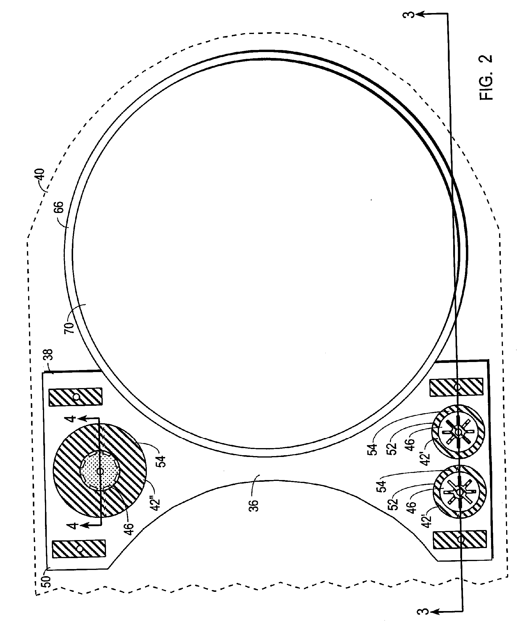
[0018] A portion of these and / or other advantages are realized in one form by a tilt sensor apparatus which includes first, second, and third planar substrates and a conductive element. The first planar substrate has a top surface on which a first conductive layer resides. The first conductive layer is formed into a bottom pattern having alternating conductive and void regions. The conductive regions of the bottom pattern are electrically coupled together. The second planar substrate overlies the top surface of the first substrate. The second substrate has an opening overlying the pattern and surrounded by an opening wall, and the second substrate has an inter-substrate conductor on the opening wall, where the inter-substrate conductor continuously occupies first and second annular tangential-contact bands in the opening wall. The third planar substrate overlies the second substrate and has a bottom surface on which a third conductive layer resides. The conductive element is positioned within the opening and configured to move within the opening to short the first conductive layer to the inter-substrate conductor when resting on the first substrate and in contact with the annular tangential-contact band.

Problems solved by technology

Moreover, in this application, as in many others, for a system to be effective many asset tags may be used, and costs for a single asset tag are desirably as low as possible because those costs are multiplied by the number of asset tags that are used in an entire system.
But mercury switches are undesirable for a variety of reasons.
Mercury switches pose a health hazard due to the presence of mercury.
Moreover, mercury switches tend to be undesirably large and far too expensive for many applications.
In applications where a need exists to sense more than one tilt angle, the large size and excessive expense problems are multiplied by the number of sensors that may be used in a single device.
But the conventional solid sensors do not include a low power, small, inexpensive, and reliable unit.
Such devices consume far too much power for many low power applications.
In addition, some solid sensors are configured with power-consuming circuitry, such as pull-up resistors, that in at least one orientation continuously consume a significant amount of power.
These devices also consume too much power for many low power applications, and are particularly undesirable for applications where the use of more than one tilt sensor would be beneficial.
This is an undesirable size characteristic because the sensor, more than the other components, prevents the device from being smaller.
In addition, in battery-powered applications, tilt sensors that consume too much power cause either an undesirably large battery to be used or require the device to include special battery compartments where replaceable batteries are located.
And, the use of replaceable batteries, and particularly batteries that require frequent replacement, is undesirable in many applications due to the nuisance factor, the costs of replacement batteries, and the excessive unreliable operational time that must be endured when battery reserves are low.
The stability and / or reliability of conventional solid sensors has been a challenging problem.
But this feature makes a continuous, robust electrical short between contacts difficult to make and maintain.
Consequently, solid sensors tend to exhibit frequent false-open errors.
False-open errors occur when the orientation of the sensor is such that a short between certain contacts should occur but does not.
In fact, solid sensors can be so sensitive to movement and so unable to make and maintain a continuous robust electrical short that they are often configured as motion detectors or jitter switches rather than tilt sensors.
In this configuration mere movement, even without altering tilt angle, causes the conductive element to produce a number of spurious shorts and opens between contacts.
Unfortunately, while such miniaturization may be desirable for motion sensing, it tends to make solid sensors less reliable and useful when used as tilt sensors.
But the conventional solutions have resulted in larger, more complex, more expensive components.
In many applications where tilt sensors are needed these solutions are undesirable due to the expense and size.
And, these solutions are particularly undesirable for applications where the use of more than one tilt sensor would be beneficial.

Method used


Image

  • Tilt Sensor Apparatus and Method Therefor
  • Tilt Sensor Apparatus and Method Therefor
  • Tilt Sensor Apparatus and Method Therefor

Examples


Embodiment Construction

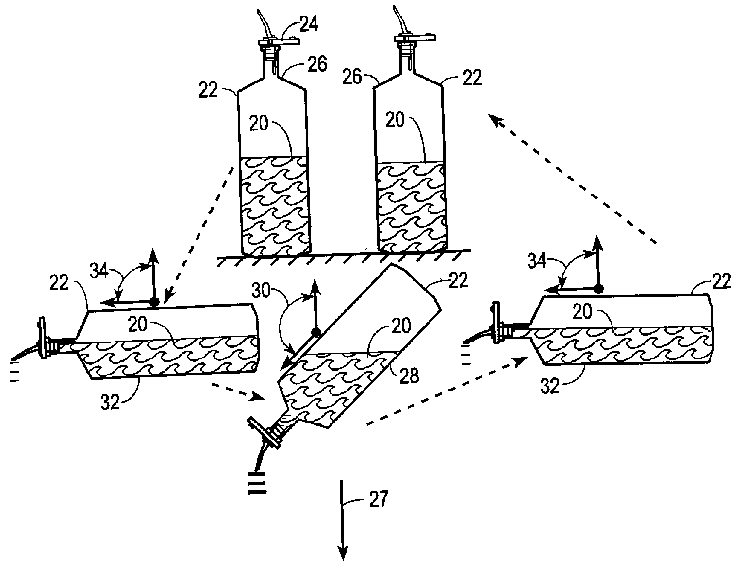
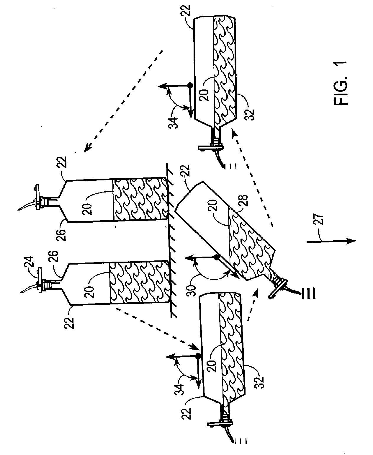
[0034]FIG. 1 shows one of many different applications where a tilt sensor apparatus configured in accordance with the teaching of the present invention may be used. In particular, FIG. 1 shows a sequence of events depicting the dispensation of a bulk product 20 in the form of a liquid from a container 22 in the form of a bottle.

[0035] In accordance with this application, product 20 is dispensed by a user, such as a bartender or other product server, when the user pours product 20 from container 22 by tilting container 22. FIG. 1 depicts three different orientations for a container 22 that is equipped with an asset tag 24. Asset tag 24 is a battery powered, electronic device that includes a tilt sensor apparatus, discussed in detail below. In an upright orientation 26, no product 20 is being dispensed from container 22. The acceleration of gravity 27 keeps product 20 in the lower portion of container 22.

[0036] When it is desired to dispense product 20 from container 22, container 2...


PUM


Abstract

A tilt sensor apparatus (36) includes one or more tilt sensors (42). Each tilt sensor (42) includes a conductive element (64) entrapped within an opening (46) formed through a middle planar substrate (38). The opening is surrounded by an opening wall (52) which is entirely covered by a conductor (54). A conductive star pattern (100′) is formed on a top planar substrate (40), and a conductive star pattern (100″) is formed on a bottom planar substrate (44). The star patterns (100) are positioned at opposing ends of the opening (46). The conductive element moves within the opening (46) as the apparatus (36) is tilted. An interrupt-driven control circuit (124) is configured to indicate a change in orientation only when a short is first detected across a contact pair (54 / 56, 54 / 60) that corresponds to an orientation opposite to a currently-indicated orientation.

Description

RELATED INVENTION [0001] The present invention claims benefit under 35 U.S.C. 119(e) to “Inventory Systems and Methods,” U.S. Provisional Patent Application Ser. No. 60 / 551,191, filed 8 Mar. 2004, and to “Inventory Systems and Methods,” U.S. Provisional Patent Application Ser. No. 60 / 650,307, filed 3 Feb. 2005, both of which are incorporated by reference herein. [0002] The present invention is a continuation-in-part of “Asset Tag with Event Detection Capabilities,” Ser. No. 10 / 795,720, filed 8 Mar. 2004, having at least one inventor in common herewith, which is incorporated by reference herein.TECHNICAL FIELD OF THE INVENTION [0003] The present invention relates generally to tilt sensors and more specifically to tilt sensors having conductive elements that move under the influence of gravity and that electrically short various contacts depending on the orientation of the sensor. BACKGROUND OF THE INVENTION [0004] Many applications detect an orientation of a device relative to the ac...

Claims


Application Information

Patent Timeline
Patent Type & Authority Applications(United States)
IPC IPC(8): G01C9/06G01C9/10G08B1/08G08B21/00H01H1/16H01H1/60H01H35/02
CPCG01C9/06G01C9/10G01C2009/068H01H35/02H01H1/16H01H1/60G01C2009/107
Inventor MORRISON, CHRISTOPHER S.
Owner NUVO HLDG
Learn More